Intel® Server Board S3420GPRX User Guide xv
List of Figures
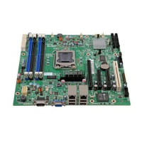
Figure 1. Intel
®
Server Board S3420GPRX............................................................................... 1
Figure 2. Server Board Connector and Component Locations ................................................. 5
Figure 3. Configuration Jumpers Location ................................................................................ 7
Figure 4. Server Board Rear I/O Layout.................................................................................... 7
Figure 5. Intel
®
SAS Entry RAID Module ................................................................................ 11
Figure 6. BIOS Recovery Jumper ........................................................................................... 17
Figure 7. Password Recovery Jumper .................................................................................... 18
Figure 8. CMOS Recovery Jumper ......................................................................................... 19
Figure 9. BMC Force Update Jumper ..................................................................................... 19
Figure 10. Installing Memory................................................................................................... 22
Figure 11. Lifting the Load Lever............................................................................................. 24
Figure 12. Open the Load Plate .............................................................................................. 24
Figure 13. Remove the Socket Protective Cover .................................................................... 25
Figure 14. Remove the Processor Protective Cover............................................................... 25
Figure 15. Installing the Processor.......................................................................................... 26
Figure 16. Close the Load Plate and Socket Lever................................................................. 26
Figure 17. Installing the Heatsink Assembly ........................................................................... 27
Figure 18. Removing the PCI Riser Assembly from the Server System ................................. 29
Figure 19. Installing a PCI Card in a Riser Card ..................................................................... 29
Figure 20. Replacing the Backup Battery................................................................................ 31
Figure 21. POST Code Diagnostic LED Location ................................................................... 33

 Loading...

