Intel® Server Board S3420GPRX User Guide 7
Figure 3. Configuration Jumpers Location
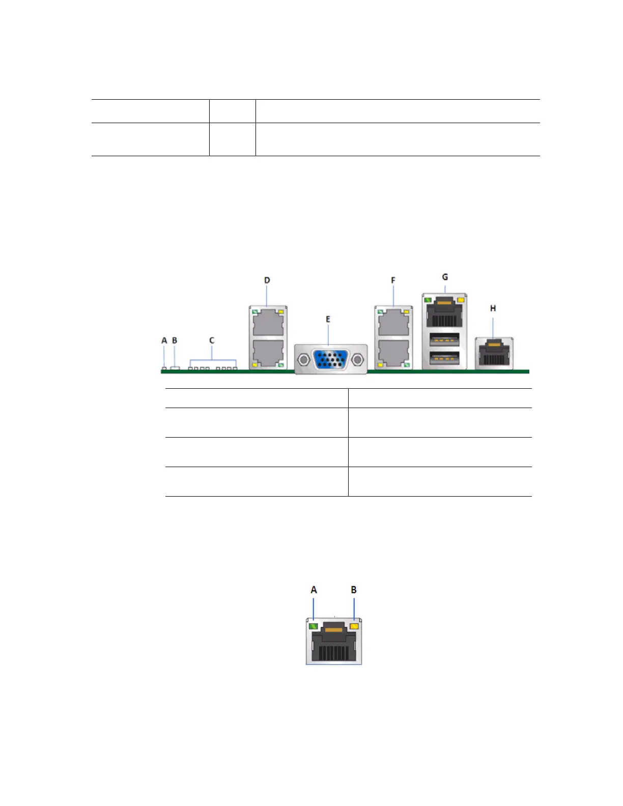
Server Board Rear I/O Layout
Figure 4. Server Board Rear I/O Layout
The NIC LEDs on the NIC connector are marked as A and B. The following table
provides the LED information.
J1D1: Chassis Intrusion 1-2 • The two pins are connected is normal state.
• The two pins are disconnected is Chassis Intrusion state.
Jumper Name Pins What will occur during a system reset..
A. System Status LED E. DB15 Video Port
B. ID LED F. Dual port RJ-45 GbE LAN Connector
(NIC3 and NIC4)
C. Diagnostics LEDs G. RJ-45 GbE(NIC5) and Dual USB
combo connector
D. Dual port RJ-45 GbE LAN Connector
(NIC1 and NIC2)
H. RJ-45 Serial Port

 Loading...


