Intel® Server Board S3420GPRX User Guide 5
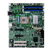
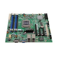
Figure 2. Server Board Connector and Component Locations
Configuration Jumpers
The server board has several jumper blocks that can be used to configure, protect, or
recover specific features of the server board.
I. Dual port RJ-45 GbE LAN
Connector (NIC1 and NIC2)
BB. SATA 0
J. Diagnostic/ID/Status LED CC. SATA 3
K. Main Power Connector DD. SATA 1
L. System FAN 4 EE. SATA 4
M. CPU Power Connector FF. SATA 2
N. CPU Fan GG. SATA 5
O. Power Supply AUX Connector HH. Internal USB connector
P. DIMM Slots II. Intel
®
RMM3 Lite
Q. System FAN 3 JJ. Front Panel Connector
R. System FAN 2 KK. Internal Serial Port
S. CPU Socket

 Loading...

