4 / 26 P/N 466-5226-EMEA-ML • REV D • ISS 17SEP18
statutory or otherwise including (but not limited to) any
warranties of merchantability or fitness for a particular purpose
with respect to the 433 products and related software. UTC
does not warrant that the 433 products and software (i.) will not
be hacked, compromised and/or circumvented, or (ii.) will
prevent or provide adequate warning or protection from break-
ins, burglary, robbery, fire or (iii.) will work properly in all
environments and applications. UTC shall not be liable towards
you or any third party for any damages whatsoever (including,
without limitation, those resulting from lost profits, lost data or
other loss of economic advantage) arising out of the use,
inability to use, or the results of use of or in any way linked to
the 433 Products and Software, whether based on warranty,
contract or tort. In no event shall UTC be liable towards you or
any third party for any amount in excess of the amount actually
received by UTC for the 433 Product and/or Software.
Regulatory information
PLACED ON THE MARKET BY:
UTC Fire & Security Americas Corporation, Inc.
3211 Progress Drive, Lincolnton, NC, 28092, USA
AUTHORIZED EU REPRESENTATIVE:
UTC Fire & Security B.V.
Kelvinstraat 7, 6003 DH Weert, Netherlands
Product warnings
and disclaimers
THESE PRODUCTS ARE INTENDED FOR SALE
TO AND INSTALLATION BY QUALIFIED
PROFESSIONALS. UTC FIRE & SECURITY
CANNOT PROVIDE ANY ASSURANCE THAT
ANY PERSON OR ENTITY BUYING ITS
PRODUCTS, INCLUDING ANY “AUTHORIZED
DEALER” OR “AUTHORIZED RESELLER”, IS
PROPERLY TRAINED OR EXPERIENCED TO
CORRECTLY INSTALL FIRE AND SECURITY
RELATED PRODUCTS.
For more information on warranty disclaimers and
product safety information, please check
https://firesecurityproducts.com/policy/product-
warning/ or scan the QR code.
EN 50131-2-6: Security Grade 2, Environmental
Class II
Tested and Certified by Telefication
European Union
directives
UTC Fire & Security hereby declares that this
device is in compliance with the applicable
requirements and provisions of all applicable rules
and regulations, including but not limited to the
Directive 2014/53/EU. For more information see:
www.utcfssecurityproducts.eu
2012/19/EU (WEEE directive): Products marked
with this symbol cannot be disposed of as
unsorted municipal waste in the European Union.
For proper recycling, return this product to your
local supplier upon the purchase of equivalent
new equipment, or dispose of it at designated
collection points. For more information see:
www.utcfssecurityproducts.eu/recycle/
Contact information
www.utcfireandsecurity.com or www.interlogix.com
For customer support, see www.utcfssecurityproducts.eu
DE: Montageanleitung
WARNUNG: Wichtige Sicherheitshinweise. Lesen Sie die
beigefügten Warnungen und Sicherheitshinweise.
Beschreibung
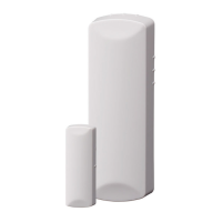
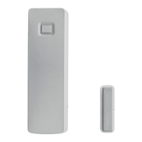
In dieser Installationsanleitung wird die Installation des 433
MHz Tür-/Fenstersensors der RF-DC101-Serie beschrieben.
Die Serie umfasst die folgenden Funksensoren:
• RF-DC101-K4 (weiß)
• RF-DC101B-K4 (mahagoni)
Sie können den Sensor auf Türen, Fenstern und sonstigen
Objekten anbringen, die sich öffnen und schließen lassen. Der
Sensor übermittelt Signale an die Einbruchmeldezentrale,
wenn ein in der Nähe des Sensors montierter Magnet vom
Sensor weg oder näher zum Sensor hin bewegt wird. Der
Sensor ist zusätzlich mit einem kombinierten Sabotagekontakt
für die Abreiß- und Öffnungsüberwachung ausgerüstet!
Abbildungen
Abbildung 1: Herausziehen des Batterie-Schutzstreifens
(1) Streifen herausziehen
Abbildung 2: Abnehmen der Sensorabdeckung
(1) Abdeckung
(2) Kleinen Schraubendreher in den Schlitz drücken und die
Abdeckung anheben
(3) Abdeckung für Schraubmontageloch
Abbildung 3: Einsetzen der Batterie
Abbildung 4: Eingangsauswahl-Steckbrücke
(1) Eingangsauswahl-Steckbrücke
Abbildung 5: Externer Kontakt Beschaltung
(1) Tür-/Fenstersensor
(2) Abschlusswiderstand
(3) Kontakte
Abbildung 6: Montagebohrungen
(T) Montageloch für T-Schraube
(T) Montageloch für L-Schraube
Abbildung 7: Sensor- und Magnetausrichtung
(1) Ausrichtungsmarkierungen
Zubehörpacks
10er Pack Distanzstück Gehäuse
für Sensor (RF-DC101SR-K4)
10er Pack Distanzstück Gehäuse
für Sensor (RF-DC101BSR-K4)
10er Pack Distanzstück Gehäuse
für Magnet (RF-DC101SM-K4)
10er Pack Distanzstück Gehäuse
für Magnet (RF-DC101BSM-K4)
Einzelner großer Magnet (RF-
DC101BM-K4)
Einzelner großer Magnet (RF-
DC101BBM-K4)
Installationsanleitung
Orientieren Sie sich an der folgenden Installationsanleitung:
• Montieren Sie den Sensor am Türrahmen. Montieren Sie
den Magneten auf der Tür. Wenn der Sensor für
 Loading...