SAVE THESE INSTRUCTIONS
Page 2
(189PO) MODEL CS7111 SALTWATER SYSTEM & FILTER PUMP ENGLISH 7.5” X 10.3” PANTONE 295U 06/28/2013
English
189
PO
S AVE THESE INSTRUCTIONS
English
Page 7
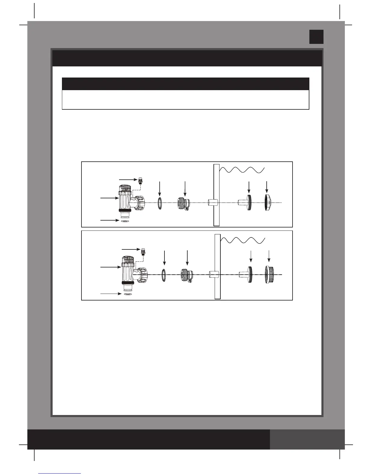
STRAINER & PLUNGER VALVE SETUP
Strainer & Plunger Valve Setup (small AGP)
The strainer grid prevents large objects from jamming and/or damaging the filter pump.
The plunger valve assembly prevents water from flowing into the filter pump while the
filter cartridge is being placed or cleaned. If your pool has an inflatable top ring, install the
strainer, nozzle and plunger valve before inflating the pool liner top ring. The parts
numbers here onward, refer to the parts depicted in the Parts List section of this manual.
To install, do the following:
1. Graspthestrainerandplungervalvemechanism.
2. In a counter-clockwise motion unscrew plunger valve union from the threaded strainer
connector (24). Be careful not to lose the step rubber washer (21).
3. Grasptheplungervalveassembly.Makesurethestepwasher(21) is in place. Connect
adaptor B (26) to plunger valve union.
4. Repeatsteps1through3fornozzleandplungervalvemechanism.
5. Remove wall plug and then insert the strainer (27 & 29) into the lower position of protruding
hose connection, and the nozzle (27 & 28) into the upper position of protruding hose
connection. Adaptor B (26) fits over the strainer connection (27) inserted into the connection.
6. Turn both plunger valve handles fully clockwise until they stop. This closes the valve,
prevents the water from flowing out of the pool.
7. The pool liner is now ready to fill with water. Consult the above-ground-pool owner's manual
for filling instructions.
IMPORTANT
The Saltwater System/Filter Pump must be installed as the last piece of pool equipment
in the water return line to the pool. This location extends the life of the titanium plates.
19
20
21 26
27 28
19
20
21 26
27 29
35
35
 Loading...