ENGINE ELECTRICALS
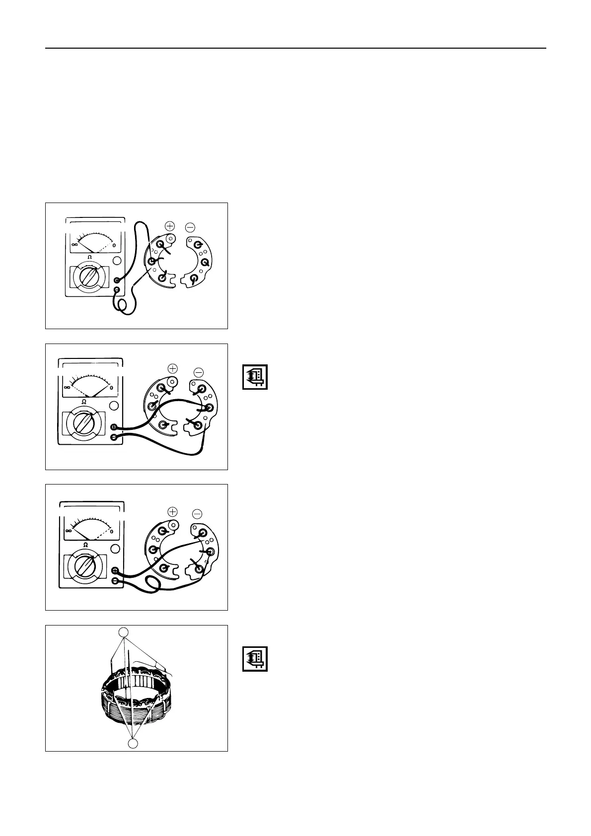
3. Note the meter reading for each diode terminal.
All of the diode should show continuity.
If a diode shows no continuity, it is open circuit. The
rectifier assembly must be replaced.
170
4. Touch the circuit tester negative probe to the recti-
fier holder.
5. Touch the circuit tester positive probe to each of the
diode terminals in turn.
6. Note the meter reading for each diode terminal.
None of the diodes should show continuity.
If a diode shows continuity, it is shorted. The recti-
fier assembly must be replaced.
Rectifier (Negative Diode) Continuity Test
Use a circuit tester to test the rectifier continuity.
1. Touch the circuit tester negative probe to the recti-
fier holder.
2. Touch the circuit tester positive probe to each of the
diode terminals in turn.
3. Note the meter reading for each diode terminal.
All of the diode should show continuity.
If a diode shows no continuity, it is open. The rec-
tifier assembly must be replaced.
4. Touch the circuit tester positive probe to the rectifier
holder.
5. Touch the circuit tester negative probe to each of the
diode terminals in turn.
6. Note the meter reading for each diode terminal.
None of the diode should show continuity.
If a diode shows continuity, it is shorted. The recti-
fier assembly must be replaced.
GOOD
BAD
Rectifier Assembly Replacement Procedure
Use the Rectifier Service Kit to replace the rectifier
assembly in the following steps.
1. Connect the three inside lead wires to the “N” termi-
nals 1.
2. Connect the three outside lead wires 2 to the out-
side terminals.
3. Wind the stator lead wires around the rectifier lead
wires (included in the Rectifier Service Kit) and sol-
der them.
 Loading...