Inspection and Installation
Copyright © Itech Electronic Co., Ltd. 10
current rated current, use several pieces of red and black test cables. For
example, the maximum current is 1,200A, then 4 pieces of 360A red and
black cables are required.
4. (Optional) Install the load input terminal cover.
5. Directly connect the other end of the red and black cables to the DUT
terminal.
Remote measurement
Remote sensing is used to counteract the effect of lead resistance. For
example, if you connect a power supply to the DC Load, the voltage at the
power supply's terminals will not be the same as the voltage at the DC Load's
terminals if there is a current flowing because of the finite resistance from the
wires. Using remote sensing, you can sense the voltage at the power supply's
terminals, effectively removing the effect of the voltage drop in the connection
wire.
When using remote sensing, the power displayed by the instrument includes
both the power dissipated inside the instrument and the power dissipated in the
leads from the power supply to the DC Load's input terminals.
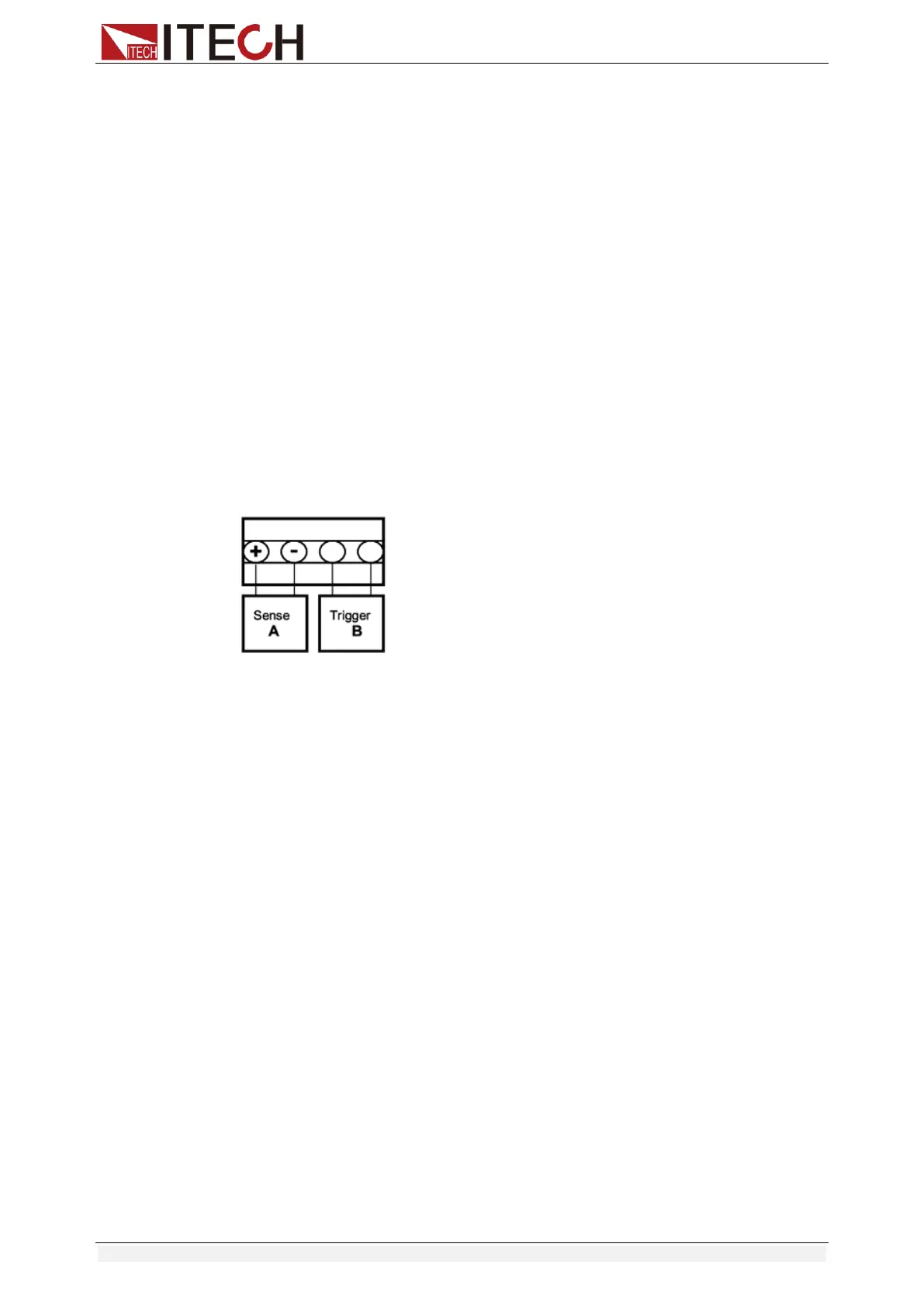
Sense terminals in the rear panel displayed as follows:
Remote Sensing: SENSE (+) and SENSE (–) are the remote sensing inputs.
By eliminating the effect of the inevitable voltage drop in the DC load leads,
remote sensing provides greater accuracy by allowing the DC load to regulate
directly at the source's output terminals.
Before using the remote measurement function, you must first set the load to
remote measurement mode. The steps are as follows:
1. Press [Shift] + [9] key into the menu.
2. Press Right/Left key to select SENSE, press [Enter] key to confirm.
3. Select ON, then the remote sense function has been set.
Note:
When not using the remote measurement function, press the OFF key to
close the remote measurement mode.
4. Refer the following diagram to connect test cables.
Wiring Diagram for Remote Sensing:
 Loading...