Installation
6 720 643 409 (2010/03)
34
9.11 Temperature sensor installation
9.11.1 Flow sensor T1
B Install the sensor in direct contact with the flow line
pipe and preferably after a 90° bend (horizontally),
according to the system diagram.
B With buffer tank: Install the sensor in the upper part
of the buffer tank, according to the system solution.
See installation instructions for the buffer tank.
9.11.2 Outdoor sensor T2
B Install the sensor on the coldest side of the house. It
must be protected from direct sunlight, ventilation air
or anything that can affect the temperature
measurement. The sensor must not be installed
directly beneath the roof.
9.11.3 Hot water sensor T3
C6 - 11: The sensor is pre-installed in the hot water
heater.
E6 - 17: The sensor must be installed when the external
hot water heater is used. Install the sensor approx 1/3
up from the bottom of the hot water heater. The sensor
must be installed over the return connection to the heat
pump.
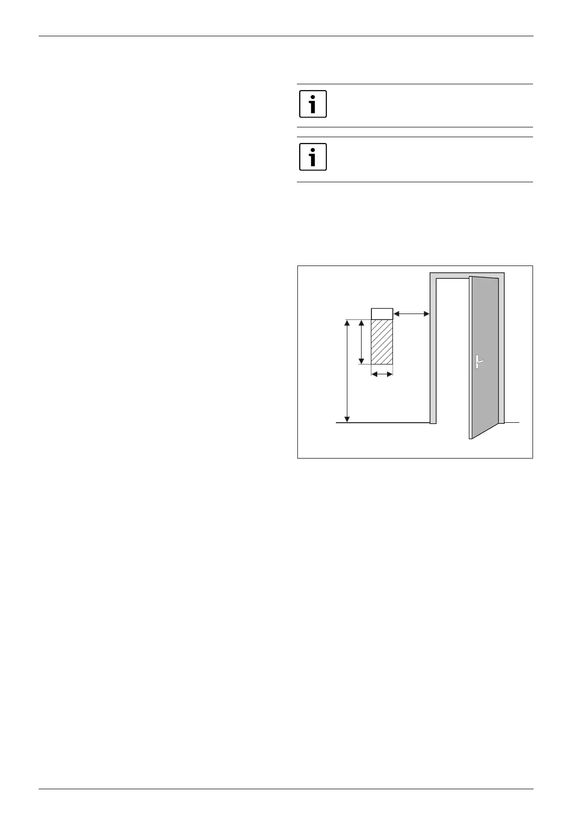
9.11.4 Room sensor T5 (accessory)
Installation location requirements:
• If possible, interior wall without drafts or heat
radiation.
• Unimpeded circulation of room air under room sensor
T5 (dotted area in image 32 must be kept clear).
Fig. 32 Recommended installation location for room
sensor T5
CANbus connected room sensor can only be
used on Circuit 1.
It is only the room where the room sensor is
located that can influence regulation of the
temperature for the relevant heating circuit.
6 720 614 366-34.1I
0,3 m
0,3 m
0,6 m
1,2 - 1,5 m
T5
 Loading...

