General
6 720 643 409 (2010/03)
7
3.9 CAN-BUS
The various circuit boards in the heat pump are joined by
a communications cable, CAN-BUS. CAN (Controller
Area Network) is a two-wire system for communication
between microprocessor based modules/circuit boards.
Suitable cable for external laying is cable LIYCY (TP)
2x2x0.5. The cable must be twisted pair and screened.
The screen must only be earthed at one end and to the
chassis.
Maximum cable length is 30 m.
CAN-BUS cable must not be laid alongside power supply
cables. Minimum distance 100 mm. They may be laid
alongside sensor cables.
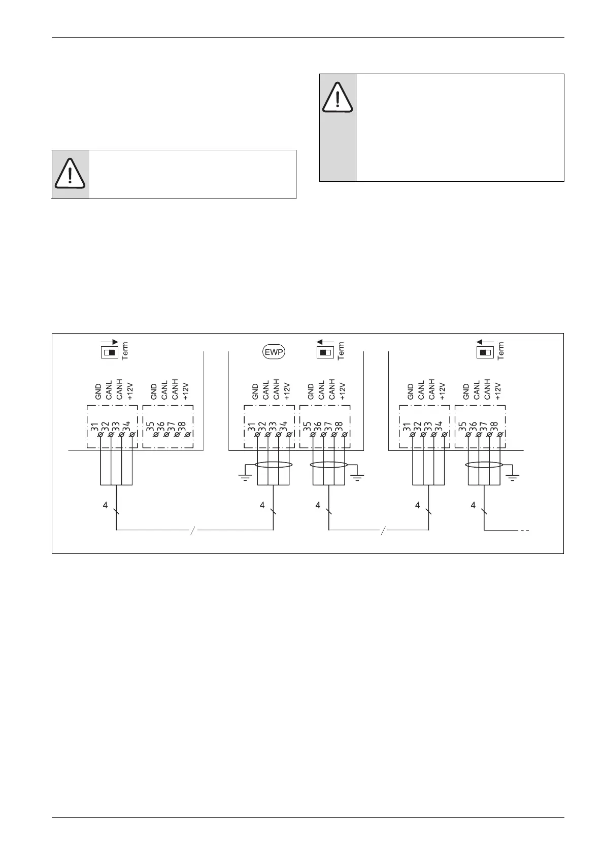
The connection between the circuit boards is by four
wires, because the 12V-supply between the circuit
boards must also be connected. The circuit boards have
markings for both the 12V and CAN-BUS connections.
Switch Term is used to mark the start and end of a CAN-
BUS loop. Ensure that the correct circuit board is
terminated and that all other switches are in the
opposite position.
Fig. 2
EWP Heat pump
GND Soil
CANL CAN low
CANH CAN high
+12V Connection 12V
CAUTION: Interference.
B The CAN-BUS cable must be screened
and laid separately from the power cable.
CAUTION: Do not mix up the 12V and CAN-
BUS connections!
The processors are destroyed if 12V is
connected to the CAN-BUS.
B Check that the four cables are connected
to the contacts with the corresponding
marking on the circuit board.
6 720 614 967-31.2I
CAN-BUS
CAN-BUS
 Loading...