Use
6 720 643 415 (2010/03)
5
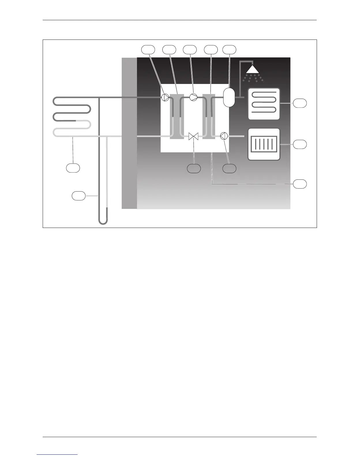
Fig. 2 Operating description
1 Heat transfer fluid pump
2 Evaporator
3 Compressor
4 Condenser
5 Water heater
6 Floor heating
7 Radiator
8 Heat pump
9 Heat carrier pump
10 Expansion valve
11 Borehole (bedrock heat)
12 Geothermal heating coil
• The collector circuit fluid, which is a mixture of water
and anti-freeze, circulates in the borehole/geothermal
heating coil in a plastic hose. The fluid collects stored
solar energy and with the help of the collector circuit
pump leads it into the heat pump and to the
evaporator. The temperature is then approximately
0°C.
• In the evaporator, the heat transfer fluid meets the
refrigerant. The refrigerant is then in a fluid state and
is at approximately -10 °C. When the refrigerant
meets the zero degree heat transfer fluid, it starts to
boil. A vapour is formed, which is then led into the
compressor. The temperature of the vapour is 0 °C.
• The pressure of the refrigerant increases in the
compressor and the temperature of the vapour rises
to approx. +100 °C. The hot gas is then forced into the
condenser.
• In the condenser, the heat is transferred to the
house’s heating system (radiators and floor heating)
and the hot water system. The vapour is cooled and
becomes fluid. The pressure in the refrigerant is still
high when it is led on to the expansion valve.
• The refrigerant pressure is lowered in the expansion
valve. At the same time, the temperature also drops to
approximately -10 °C. When the refrigerant passes
the evaporator it changes to vapour again.
• The heat transfer fluid is led out from the heat pump
to the borehole/geothermal heating coil to collect
new stored solar energy. The temperature of the fluid
is approx. -3 °C.
1 2 3 4
5
6
7
8
11
910
12
6 720 614 540-02.3I
 Loading...


