Control panel
6 720 643 415 (2010/03)
8
5 Control panel
Settings for the control of the heat pump are made with
the control unit's control panel, which also provides
information about current status.
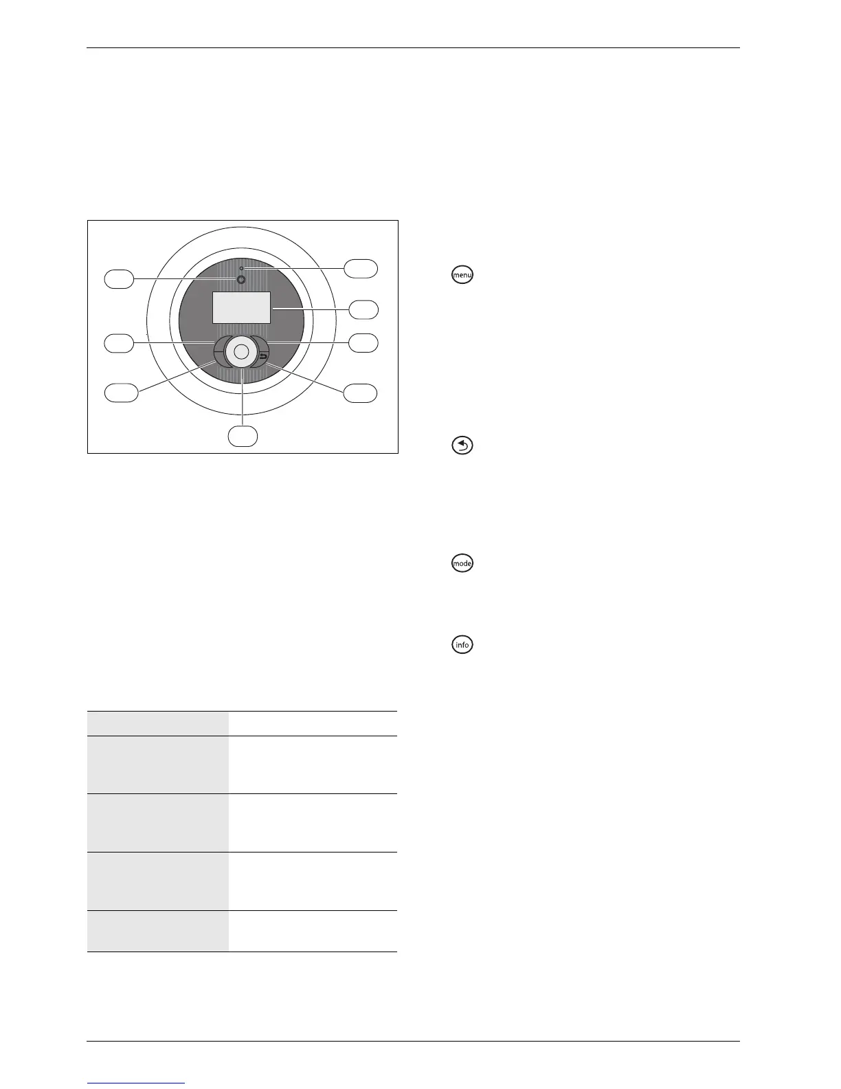
5.1 Panel overview
Fig. 3 Control panel
1 On/Off button
2 Mode button
3 Info button
4 Menu dial
5 Status lamp
6 Return button
7 Menu button
8 Menu display
5.2 Power switch (ON/OFF)
Use the On/Off button to switch the heat pump on and
off.
5.3 Status lamp
5.4 Menu display
Use the menu display in order to:
• See information from the heat pump.
• See available menus.
• Change set values.
5.5 Menu button and menu dial
Use to get from Initial menu to the menus. Use the
menu dial in order to:
• Navigate the menus and get to the setting displays.
– Turn the dial to see more menus on the same level
or change a set value.
– Press the dial to change to a lower menu level or
save a change.
5.6 Return button
Use to:
• Go back to the previous menu level.
• Leave a setting display without changing the set
value.
5.7 Mode button
Use to change type of operation.
• Change type of operation.
5.8 Info button
Use to see information from the control unit about
operating mode, temperature, program version, etc.
The lamp lights green. The heat pump is running.
The lamp flashes red. There is an alarm which
has not been
acknowledged
The lamp lights red. The alarm has been
acknowledged but the
alarm cause remains
Lamp flashes slowly
green, menu window
not lit.
The heat pump is in stand-
by mode
1)
.
1) Stand-by means that the heat pump is running but no
heating or hot water demand exists.
The lamp and menu
display not lit.
No voltage to control unit.
Tab. 2 Lamp functions
menu
mode
i
6 720 641 855-08.1I
5
6
2
8
1
7
4
3
 Loading...


