J-100
8. Connect wires, color to color, on terminal blocks TB1 and TB3
(Figure C, page 15). TIGHTEN SECURELY! All wires must be
hooked up securely or damage could result.
9. Install control box door and screws and reinstall the cabinet side
panels.
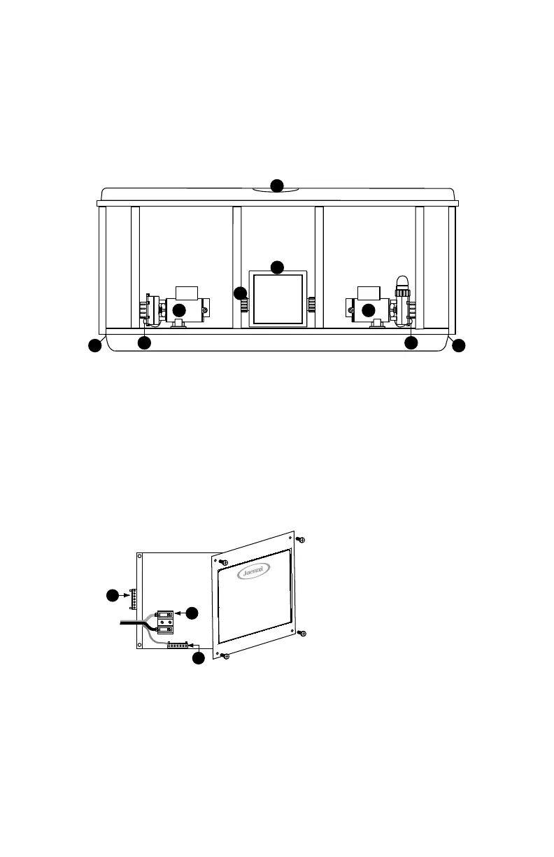
Figure A
Equipment Area
Note: Equipment location (such as pumps, drain, heater etc.) varies by model.
1. Control Box 5. Pump Drain Plug
2. Power Supply Inlet(s) 6. 1-Speed Pump
3. 2-Speed Pump 7. Control Panel
4. Heater
Figure B
Control Box
TB1
3
2
1
1. Terminal Block
2. Bonding Lug
3. Grounding Terminal
14
 Loading...