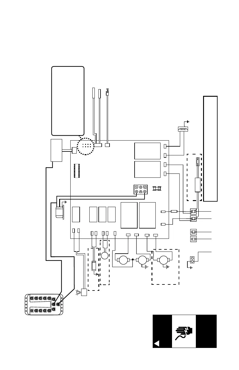
This wiring diagram is used for the 230V 50 Hz Export spa models.
Light DCU
1
2
3
4
5
6
7
8
9
10
POWER
EXP BAR EXP BAR
BRN
BLU
C
Circ.
Pump
Stereo
Power Supply
CLEARRAY
GRN
TB1
BLU
BLU
J6
BRN
J5
BRN
BLU
BLK
BLU
BRN
BLU
BRN
BLU BLU
BRN BRN
BRN
2
1
Flow Sensor
Hi - limit / freeze sensor
Temperature sensor
J1
J2
J3
F1
20A, 250V
SC-20
Pump 1
Pump 2
Transformer
230 VAC
J4
F1
JP1
4
2
3
1
6 5
8 7
HI
HI
LO
Control Panel
J20
K1
K2
K3
K4
K5
K6 K7 K8
J21
J11
J12
J13
J14
J15
J16
J17
J18
J19
J7 J8
J9
J10
Heater
2.7 kW @
230 VAC
WHT
BLK
LED Lighting
System DCU
Logic Jumper Settings
JP1 1-2 ON = 20A Logic
JP1 1-2 OFF = 30A Logic
JP1 3-4 ON = 2 Pump Operation
JP1 3-4 OFF = 1 Pump Operation
JP1 5-6 ON = 40A Logic (Remove JP1 1-2 Jumper)
JP1 5-6 OFF = Leave Off for 20A or 30A Logic
JP1 7-8 ON = Celsius Temperature Display
JP1 7-8 OFF = Fahrenheit Temperature Display
Mini-Din Cable provides
constant 12 VAC from
yellow transformer wires
Mini-Din Control
Panel Cable
Ports 1-10
power spa
lights, waterfall
lights and step
lights on
applicable
models
OR
(not offered on
all models)
(not offered on all models)
(not offered on all models)
TB2
BRNBLU
230 VAC 3-Wire Connection (50 Hz, 1-Phase Service), 1 Pump=15A/21A, 2 Pump=15A/29A,
USE COPPER CONDUCTORS ONLY. WIRE SIZE MUST MEET NEC RECOMMENDATONS
AND/OR LOCAL CODES AND IS DETERMINED BY MAXIMUM CURRENT DRAW AND
LENGTH OF RUN.
(Not offered on
all models)
 Loading...