Page 12
AquaLink
®
Touch™ and Operation Installation Manual
Section 4. Wireless AquaLink Touch
Installation
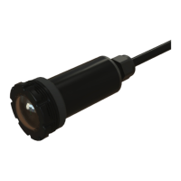
4.1 AquaLink Touch Transceiver J-Box
Cable Installation
Installation Considerations. The transceivers will
transmit through walls and around corners. Steel
framing, aluminum siding, wrought iron, cyclone
fences, lead ed glass, and other 900 MHz frequency
items may inhibit/prevent com mu ni ca tion between the
AquaL ink
®
RS AquaLink Touch wireless control and
the power center. The trans ceiv ers do not require line
of sight to communicate.
WARNING
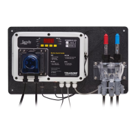
Potentially high voltages in the AquaLink RS power
center can create dangerous electrical hazards,
possibly causing death, serious injury or property
damage. Turn off power at the main circuit feeding
the AquaLink RS power center to disconnect the
power center from the system.
Never run high voltage and low voltage in the same
con duit.
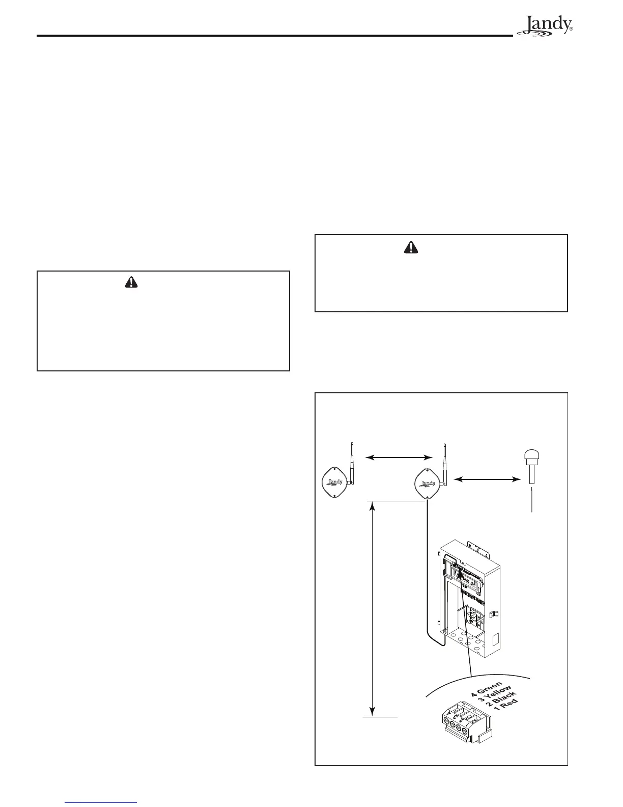
1. Turn off all power to the power center.
2. Mount the outdoor transceiver J-box at least six (6)
feet (1,8 m) above the ground at least eight (8) feet
(2,4 m) from any motor or air blowers that may
be in the vicinity, and at least fi ve (5) feet (1,5 m)
away from other transceiver J-boxes.
3. The transceiver J-box antenna must point towards
the sky.
NOTE To improve performance of the transceiver,
mount the J-box more than six (6) feet (1,8 m)
above the ground.
4. Open the door to the power center and remove the
dead panel.
5. Pull cable through the knockout with the Heyco
fi tting and into the low voltage compartment. See
Figure 13.
6. Strip back the insulation jacket of the cable
approximately 6" (15 cm).
7. Strip each wire ¼" (6 mm) and connect to the
red, 4-pin connector on the power center PCB. A
mul ti plex kit (part number 6584) may be required if
there are more than two (2) cables running to a red,
4-pin connector on the PCB.
8. Install the dead panel to the power center and
restore all power.
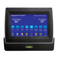
4.2 AquaLink Touch Charger Installation
1. Plug the charger into a wall socket.
NOTE The charger plug must be installed near the wall
socket and easily accessible.
2. Charge the wireless controller for 24 hours before
removing from the power supply/charger (the
system is operational while charging).
WARNING
Only use the battery pack provided with the equipment.
Only use the battery charger provided with the
equipment. RISK OF EXPLOSION IF BATTERY IS
REPLACED BY AN INCORRECT TYPE.
4.3 Changing the Frequency Channel
See Section 6.5.5, "RF Channel (For wireless units
only)".
Figure 13. Outdoor Transceiver J-box Installation
Transceiver J-boxes
(Antennae must face upward)
Minimum
8’ (2.4 m)
Air Blower
6’
(1,8 m)
Ground Level
Red 4-Pin Terminal Bar
Minimum
5’ (1.5 m)
Low Voltage
Area
 Loading...