Page 8
ENGLISH
Wireless Handheld Remote | Installation and Operation Manual
SECTION 3. INSTALLATION
The transceiver will transmit
through walls. However, steel
framing, aluminum siding, stucco
wrought iron, chain link fences,
lead ed glass, and other 900 MHz
frequency items may inhibit or
prevent com mu ni ca tion between the
Handheld Remote and the Power
Center. To optimize communication,
install trans ceiv ers in a location that
minimizes interference.
WARNING
Potentially high voltages in AquaLink
®
Power Centers can create
dangerous electrical hazards, possibly causing death, serious injury or
property damage. Turn off power at the main circuit feeding the Power
Center to disconnect the Power Center from the system.
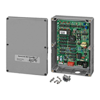
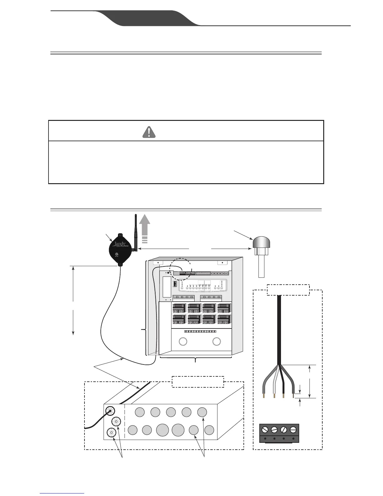
3.1 TRANSCEIVER J-BOX CONNECTION TO POWER
CENTER PCB
Low Voltage
Raceway
6’ Min.
To
Ground Level
Blower or Other Equipment
Low Voltage
Cable
Low Voltage
Knockouts with Heyco Fittings
High Voltage Raceway
High Voltage Knockouts
for Conduit
Transceiver J-Box
BOTTOM VIEW
8’ Min.
18-Channel RF Transceiver
R0686300
For AquaLink
®
20-Channel
Handheld Wireless Remote (P/N R0687300)
Technical Support
USA: 800.822.7933
AUS: 1800.688.552
3032401
FCC ID: RIR400121
IC: 10837A-400121
Rated: 10V DC
Input: 90 mA
MODEL NO. 8252
MADE IN CHINA
“A”
3 Yellow
1 Red
2 Black
4 Green
1/4”
6”
DETAIL “A”
 Loading...