INSTALLATION
WARNING: In many
cases,
installation of the
JBL
5234A
Electronic
Frequency Dividing Network involves opening
the cover to gain
access
to interal circuit modules and
programming
switches.
In addition, conversion of the line
voltage may involve installation of a new power
cord.
Since
dangerous
AC voltages exist inside the unit, caution must
be
exercised.
These
instructions are intended for use by
qualified
service
personnel only.
Installation of Standard
Crossover
Frequency Modules
The
dividing network is shipped with a pair of
52-5120
crossover modules
(cards),
each with two
100
ohm resistors that convert each channel
into
a
one-input,
two-output
unity gain distribution
amplifier. The two cards therefore equip the
5234A
to function as a pair of independent one-
input,
two-output
amplifiers; the network inputs
can
be paralleled to provide four outputs from a
single
source. The
HIGH
outputs will be at unity
gain when the
HIGH
FREQUENCY
LEVEL
con-
trols are set at maximum (the controls can be
turned down if
loss
is desired).
Prior
to its use as a frequency dividing network,
these
jumpered "blank" cards must be removed
from the 5234Aand the appropriate frequency
selection
cards must be installed in their place.
To
install the
cards:
1.
Place
the 5234A upside down on a soft
surface,
remove the two Phillips-head
screws
from
either side of the
case,
and
lift
the
bottom
cover
from the
chassis
(Figure 3).
2.
Remove the old crossover cards by
lifting
both
sides
of a card simultaneously and gently
(Figure
4). Friction from the three mounting pins
and
the electrical connector must be overcome.
3.
Align the three holes in each new crossover
card
with the corresponding mounting pins on the
main printed circuit board (Figure 5). The com-
ponents on the card should face toward the
chassis,
with the frequency designation label toward the
front
panel.
4.
As each card is gently pressed against the
mounting pin stops (roughly 6 mm, 1/4 in),
electrical
connection will be made between the
card
connector and six pins on the printed circuit
board.
5.
Unless
LF programming is to be reset (refer to
next
topic in this manual), replace the
bottom
cover,
observing the proper orientation. The cover
will not
seat
properly in the
chassis
if rotated 180°
Secure
the cover with the four
screws.
The unit is
now ready for mounting and connection of the
various
inputs and outputs.
NOTE:
Operation of the 5234A without a
crossover
card
will not damage the
unit,
although neither will it
pass
any
audio
signals.
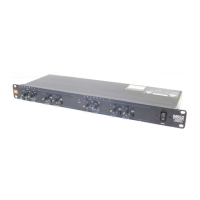
Figure
3 — Remove
These
Screws
to Lift Off the Bottom Cover
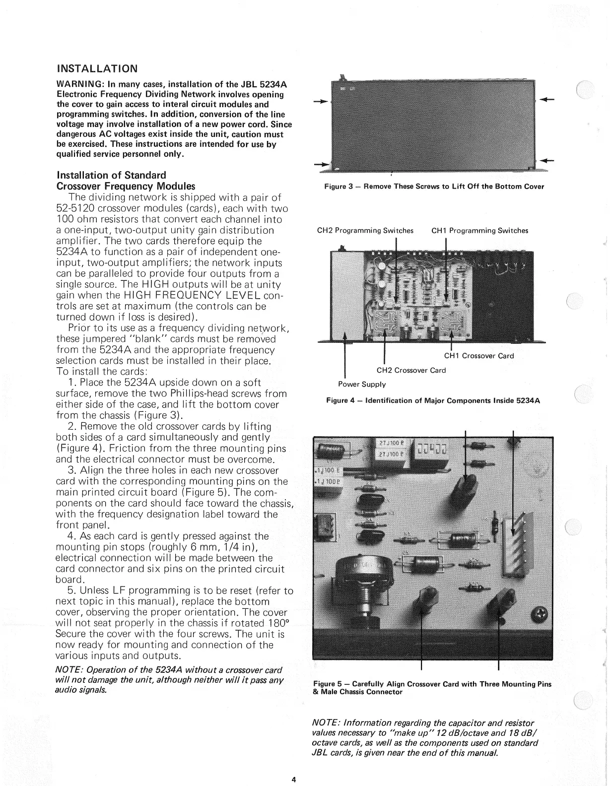
Figure
5 — Carefully Align
Crossover
Card with Three Mounting
Pins
& Male
Chassis
Connector
NOTE:
Information regarding the capacitor and
resistor
values
necessary
to "make up" 12
dB/octave
and 18 dB/
octave
cards,
as well as the components
used
on standard
JBL
cards,
is given near the end of this manual.
4
CH1
Crossover Card
CH2
Crossover Card
Power
Supply
Figure
4 — Identification of Major Components Inside 5234A
CH2
Programming Switches
CH1
Programming Switches
 Loading...