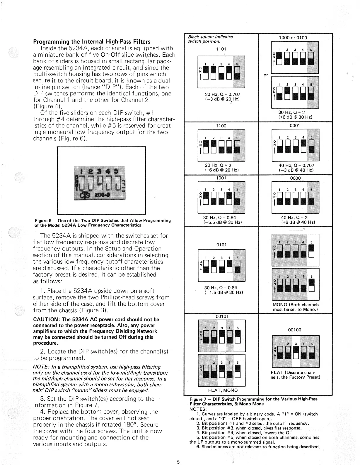
Programming the Internal High-Pass Filters
Inside the 5234A, each channel is equipped
with
a
miniature bank of five On-Off slide switches.
Each
bank of sliders is housed in small rectangular pack-
age resembling an
integrated
circuit, and since the
multi-switch housing has two rows of pins which
secure
it to the circuit board, it is known as a dual
in-line pin switch (hence
"DIP").
Each
of the two
DIP
switches performs the identical functions, one
for Channel 1 and the
other
for Channel 2
(Figure 4).
Of the five sliders on each DIP switch, #1
through
#4 determine the high-pass
filter
character-
istics
of the channel, while #5 is reserved for creat-
ing a monaural low frequency
output
for the two
channels
(Figure 6).
The
5234A is shipped
with
the switches set for
flat
low frequency response and discrete low
frequency
outputs.
In the Setup and Operation
section of this manual, considerations in selecting
the various low frequency
cutoff
characteristics
are
discussed. If a characteristic
other
than the
factory preset is desired, it can be established
as
follows:
1.
Place the 5234A upside
down
on a soft
surface,
remove the two Phillips-head screws
from
either side of the
case,
and
lift
the
bottom
cover
from
the
chassis
(Figure 3).
CAUTION:
The 5234A AC power cord should not be
connected to the power receptacle. Also, any power
amplifiers to which the Frequency Dividing
Network
may be connected should be turned Off during this
procedure.
2.
Locate the DIP. switch(es) for the channel(s)
to be programmed.
NOTE:
In a
triamplified
system,
use high-pass filtering
only on the channel
used
for the low-mid/high transition;
the mid/high channel should be set for
flat
response.
In a
biamplified system
with
a mono subwoofer, both chan-
nels'
DIP switch "mono"sliders must be engaged.
3.
Set the DIP switch(es) according to the
information
in Figure 7.
4.
Replace, the
bottom
cover, observing the
proper orientation. The cover
will
not seat
properly
in the
chassis
if
rotated
180°. Secure
the cover
with
the
four
screws. The
unit
is now
ready for
mounting
and connection of the
various inputs and
outputs.
Black
square indicates
switch
position.
20 Hz, Q= 0.707
(-3dB@20 Hz)
1100
20 Hz, Q = 2
(+6dB@20Hz)
1001
30 Hz, Q = 0.54
(-5.5dB@30 Hz)
0101
30 Hz, Q = 0.84
(-1.5dB@30Hz)
00101
FLAT,
MONO
1000 or 0100
30 Hz, Q = 2
(+6 dB
@
30 Hz)
0001
40 Hz, Q= 0.707
(-3dB@40Hz)
0000
40 Hz, Q = 2
(+6dB@40Hz)
MONO (Both channels
must be set to
Mono.)
00100
FLAT
(Discrete chan-
nels,
the Factory Preset)
Figure 7 — DIP Switch Programming for the Various High-Pass
Filter Characteristics, &
Mono
Mode
NOTES:
1.
Curves are labeled by a binary code. A
"1"
= ON (switch
closed),
and a "0" = OFF (switch open).
2.
Bit positions #1 and #2 select the
cutoff
frequency.
3.
Bit
position
#3, when closed, gives
flat
response.
4.
Bit
position
#4, when closed, lowers the Q.
5.
Bit
position
#5, when closed on
both
channels, combines
the LF
outputs
to a
mono
summed signal.
6.
Shaded areas are not relevant to
function
being described.
5
1101
Figure 6 — One of the Two DIP Switches
that
Allow Programming
of the
Model
5234A Low Frequency Characteristics
 Loading...