EasyManua.ls Logo

JBL 6290 User Manual

JBL 6290
30 pages
To Next Page IconTo Next Page
To Previous Page IconTo Previous Page
Page #24 background imageLoading...
Page #24 background image
functions
as
a
non-inverting
current to
voltage
converter
with
exceedingly
high low
frequency
voltage
gain and a
dominant
pole at
24
kHz
with an
8
ohm
load. Closed
loop
gain rolls
off
at
6
dB/octave to
the
unity
gain
crossover (
somewhere
beyond
2
Mhz
).
A
conventional
bias
transistor
with
delta
Vbe
multiplication
spreads the
collectors of
the
upper
and
lower
transconductance
amplifiers to
compensate
for the Vbe drop
of the
output
devices.
The
bias
transistor
is,
of
course,
fastened
to
the heatsink
assembly in
order to
temperature
track
the
output
devices.
The output
stage
is
a
full
complementary
Darlington
configuration. Again, full
complementary
is
chosen
to
assure
symmetrical
amplification.
The output
short
circuit
protection
is the
simplest
kind.
Only non-feedback type
current
sensing is
used.
Under
overload
conditions,
current is
shunted from the
collectors
of
the
transconductance
stage to
the
output
line and
into
the load.
This
protects
the
output
stage
from
destruction.
4.4
RELAY
DRIVER/OUTPUT
DC DETECTQB
The output
relay
K1
is
driven
by
transistors Q19
and Q24.
Diode GR1 1
shorts
out
back
EMF
from the
relay
coil.
Resistor
R28
provides a
current source
for the STANDBY
indicator
when the
relay
is open.
The
emitter of Q19
Is
clamped to
ground
by
Q24 when
the
-15
VDC
is
fully
charged. Q19
turns
ON
when the
base
voltage
becomes
positive with
respect
to
ground.
When Q19
is ON the
collector
becomes
approximately
0
volts
and the
relay
turns
on.
Current
which would
have gone
to the
STANDBY indicator is
shunted
by
diode
CR10.
The
relay is
driven by
IC3B
through
current
limiting
resistor R43.
IC3B and
associated
components
perform
several
functions:
capacitor
C51
detects
+15 VDC
voltage
change
which is
rectified
and
stored
by
CR12,
CR19
and Cl
3
to
provide turn-on
delay;
resistor
R33
senses
DC on
the
amplifier
output;
and
resistor
R46
with thermistor
R47
determines
overtemperature
conditions.
These
circuits are
diode OR-ed to
the
inputs
of
the
operational
amplifier
which is
configured as
a
Schmitt
trigger.
Resistor R44
negates
input
offset
and
R42
provides
hysteresis
for
ail circuits except
overtemperature,
for which
resistor
R45
provides
hysteresis.
Positive
voltage
on the output
of
the
operational
amplifier causes
the
relay
to
turn on,
negative voltage
turns It
off.
4.5
CLIP_CIBCUJI
In the
clip detector
circuit,
transistor Q18
is
normally turned
ON,
shunting current
away
from
CLIP
LED DS3.
The
peak output
voltage
of
the
amplifier
is sensed
through
diode
CR9 and
resistor
R24
and turns
the
transistor
OFF,
which turns
the LED ON.
Capacitor
Cl
provides
peak
stretching,
enabling
transient,
short duration
peaks
to
be
seen.
4.6
POWER SUPPLY
The
power supply is
conventional.
The
AC
voltage
from the transformer is
rectified
by
the
bridge
rectifier
and filtered by
the
storage
capacitors.
The high voltage,
high
current DC
Is used
in the voltage
and output
amplifier
stages.
An
additional
winding
from
IV-2
Question and Answer IconNeed help?

Do you have a question about the JBL 6290 and is the answer not in the manual?

JBL 6290 Specifications

General IconGeneral
BrandJBL
Model6290
CategoryAmplifier
LanguageEnglish

Summary

Introduction

Specifications

Details output power, frequency response, noise, input impedance, maximum input level, and sensitivity.

AC Power

Specifies voltage requirements for USA/Canada and identifies voltage-wired units.

External Connections

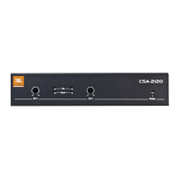
Details input and output connection methods using XL-type, phone jacks, and barrier strips.

Appropriately Rated Loads

Guidance on matching amplifier power to loudspeaker impedance and power handling capabilities.

Grounding

Explains safe mechanical ground connection, ground loops, and troubleshooting methods.

Operating Instructions

Turn On and System Check

Procedure for powering up the amplifier and verifying system operation via standby indicators.

Clip Indicators

Explains the function of CLIP indicators and how to respond to overload conditions.

Maintenance

Related product manuals