1 2 3 4
89
5 6 7
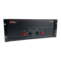
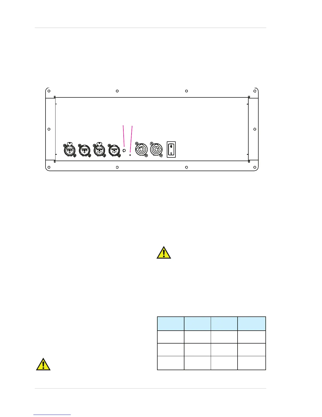
3. CONNECTOR AND WIRING DETAILS
CONNECTOR PANEL DIAGRAM
1 Audio input connector
2 Audio link connector
3 RS-485 network input connector
4 RS-485 network link connector
5 AC mains input connector
6 AC mains link connector
7 Mains switch/resettable circuit breaker
8 Status LED
9 Reset and Preset Control (access hole)
AC MAINS
Two Neutrik
®
PowerCon
®
chassis connectors are
fitted to the UniAmp 700. The Input connector
(coloured blue) is a Neutrik
®
Type A, and is intend-
ed for connection of the AC mains supply; the Link
connector (coloured grey) is a Neutrik
®
Type B, and
is to facilitate connection to another module in an
adjacent enclosure.
Note that the Link connector is not inde-
pendently fused.
User Guide - AXYS
®
UniAmp Power Amplifier Module , Model 700
The full-load power consumption of the amplifier
module is 700 VA under typical normal operating
conditions. When “daisy-chaining” AC mains between
several enclosures of the same type using the Input
and Link connectors, ensure that the current capacity of
the supply is sufficient for ALL amplifiers in the chain,
and additionally, that the total current drawn by all the
amplifiers does not exceed 20 A (the maximum rated
current of the PowerCon
®
connectors).
In practice, this means that the maximumnumber
of amplifiers (including the first one) that may
be daisy-chained in this way is six (230 V operation) or
three (115 V operation).
Only wire AC mains connectors according to the table
below:
6 200905/UAUG_v1.0
PIN CONNECT
COLOUR
(Europe)
COLOR
(US)
L Live Brown Black
N Neutral Blue White
Earth
(Ground)
Geen/Yellow Green
 Loading...