15
2.6 Wiring Your Audio System
100V ~
120V ~
220V-240V ~
50/60Hz 225W
OUTPUTS
100V
70V
COM
CLASS 2 OUTPUT WIRING PERMITTED
REMOTE
(CSR-V)
VOX
INPUT1
FRONT
PANEL
MUSICINPUT2 INPUT3
INPUT4
MONO
SUM
MONO
SUM
OFF
OFF
LINE
LINE
OFF
LINE
LINE
OFF
1-70V/100V Output
2-Chime
3-Input 1 Line/Mic
4-Input 2 Line/Mic
5-Input 2 Phantom
6-Input 3 Line/Mic
7-Input 4 Line/Mic
8-Input 4 Phantom
PRIORITY
(Input 2)
ON
ON
MIC
MIC
ON
MIC
MIC
ON
MADE IN CHINA
CAUTION
RISK OF ELECTRIC SHOCK
DO NOT OPEN
WARNING
- TO REDUCE THE RISK OF FIRE OR ELECTRICAL SHOCK, DO NOT EXPOSE THIS EQUIPMENT TO RAIN OR MOISTURE.
AVERTISSEMENT
- RISQUE DE CHOC ÉLECTRIQUE - NE PAS OUVRIR.
AVERTISSEMENT
- ÉNERGIE ÉLECTRIQUE DANGEREUSE VOIR LA NOTICE DE FONCTIONNEMENT.
VMA 1240
THIS DEVICE COMPLIES WITH PART 15 OF THE FCC RULES. OPERATION IS SUBJECT TO THE FOLLOWING CONDITIONS:
1) THIS DEVICE MAY NOT CAUSE HARMFUL INTERFERENCE, AND
2) THIS DEVICE MUST ACCEPT ANY INTERFERENCE RECEIVED, INCLUDING INTERFERENCE THAT MAY CAUSE
UNDESIRED OPERATION.
CONTAINS FCC ID: API-MB8811VMA
CONTAINS IC: 6132A-MB8811VMA
CMIIT ID: 2016DJ2941
HARMAN INTERNATIONAL
1718 W. Mishawaka Rd.,
Elkhart, IN 46517
Apparatet må tilkoples jordet stikkontakt
Apparaten skall anslutas till jordat uttag
Laite on liitettävä suojakoskettimilla
varustettuun pistorasiaan
CONFORMS TO
UL STD .60065
CERTIFIED TO CSA STD.
C22.2 NO .60065
ATTENTION - POUR RÉDUIRE LE
RISQUE DE CHOCK ÉLECTRIQUE, LA
FICHE CENTRALE DE LA PRISE DOIT
ÊTRE BRANCHÉE POUR MAINTENIR
LA MISE À LA TERRE.
CAUTION - TO REDUCE THE RISK OF
ELECTRIC SHOCK, GROUNDING OF
THE CENTER PIN OF THE PLUG MUST
BE MAINTAINED.
CAN-ICES-3(B)/NMB-3(B)
LEVEL
CSR-V
CD /OPTICAL
SPK 1 + 2 VIRTUAL
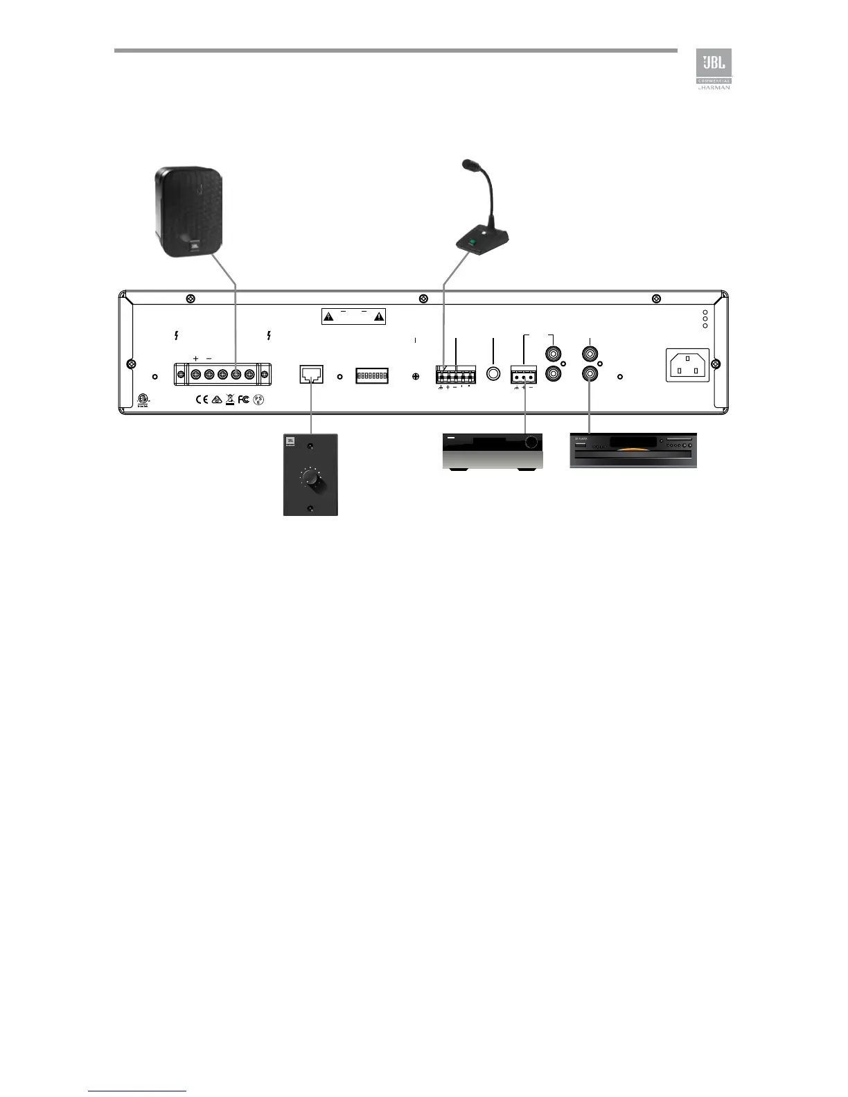
Figure 2.6.1 Wiring Audio System
Typical input and output connections are shown in Figure 2.6.1.
INPUTS: Connect input wiring for both channels using either the RCA or the
Euroblock input for each channel.
OUTPUTS: You may use either low impedance or high impedance speakers. Always
be sure to maintain the proper polarity when wiring speakers.
Low Impedance Speakers should be driven using the +/- pins of the amplier output
connector. The minimum impedance an amplier channel can drive is 4 Ohms.
Therefore, you can connect up to four 16 Ohm speakers, two 8 Ohm speakers or one
4 Ohm speaker to an amplier output channel.
High Impedance Speakers should be driven using the appropriate (70V or 100V) pin
to speaker (+) and the COM pin to speaker (-) of the amplier output connector. The
minimum impedance that can be driven from each output is provided in Appendix
A. Note that the HI-Z switch must be ON in order to provide audio to the high
impedance outputs.
WARNING: Do not connect to both low impedance speakers and high impedance
speakers from the same audio output channel.
 Loading...