15c-1, 16c-1, 18z-1, 19c-1, 19c-1 PC 7
Fig 3
Operation
Transporting the Machine
104 9831/2900-1 104
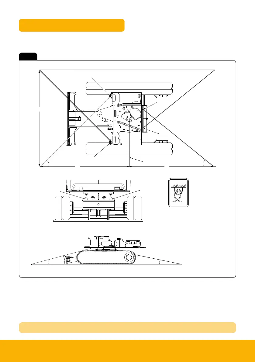
Figure 90. Method 3
J
B
B
B
B
A
A
G
F
C
D
H
I
A Front slew spine tie-down point B Rear slew spine tie-down point
C Angle = 41° to 46° D Angle = 30° to 45°
E Angle = 9° to 15° F Length = 2,253mm to 1,943mm
G Length = 2,277mm to 1,670mm H Length = 2,500mm
J Slew ring centre line K Tie down decal
15.1. Make sure the straps are arranged at the correct angles.
15.2. Set the correct strap length from centre of the trackframe to end of the straps.
15.3. Apply the correct lashing forces. Refer to Table 10.
16. Close the doors, windows, and covers on the machine and lock where possible to prevent accidental
opening during transport.
17. Remove both ramps and attach them in their transport position.
18. Raise any jacks to their transport position.
A Front slew spine tie-down point
C Angle = 35° to 46°
E Angle = 9° to 15°
G Length = 2,282mm to 1,670mm
I Slew ring centre line
B Rear slew spine tie-down point
D Angle = 35° to 45°
F Length = 2,499mm to 1,846mm
H Length = 2 ,500mm
J Tie down decal
Tie Down Points
Method 2
REFER TO OPERATORS MANUAL TRANSPORTING MACHINE

 Loading...