About the Product
Operator Station
14 9821/3700-4 14
Operator Station
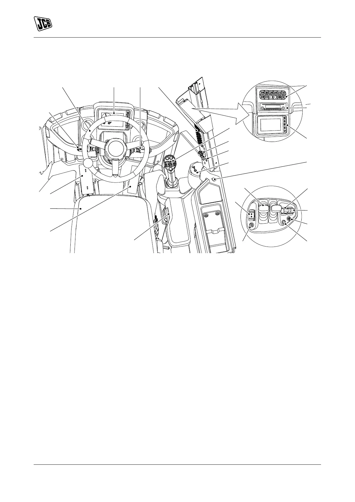
Component Locations
Figure 9.
A Transmission Refer to: Drive Controls. B Steering wheel Refer to: Steering Wheel.
C Front display panel Refer to: Instruments. D Multi purpose steering column switch Refer to:
Multi-Purpose Switch.
E Console switches Refer to: Console Switches. F ATC (Automatic Temperature Control) panel or
optional manual HVAC (Heating Ventilation Air
Conditioning) controls Refer to: Air-Conditioning
Controls.
G Radio H Secondary display panel (option) Refer to:
Instruments.
J Proportional lever controls Refer to: Operating
Levers/Pedals.
K Rotary switch panel Refer to: Instruments.
L Park brake switch Refer to: Park Brake. M Coffee machine (option)
N Starter switch Refer to: Ignition Switch. P Forward reverse switch Refer to: Forward,
Neutral and Reverse Switch.
Q Multi lever controls Refer to: Drive Controls. R Primary auxiliary controller (option)Refer to:
Auxiliary Circuit Controls.
S Secondary auxiliary controller (option) T Differential lock
U Horn V Transmission kickdown switch Refer to:
Transmission Kickdown Switch.
W Armrest Refer to: Armrest. X Accelerator pedal Refer to: Accelerator Pedal.
Y Seat Refer to: Operator Seat. Z Service brake pedal Refer to: Service Brake
Pedal.

 Loading...