About the Product
Operator Station
16 9831/0050-6 16
Operator Station
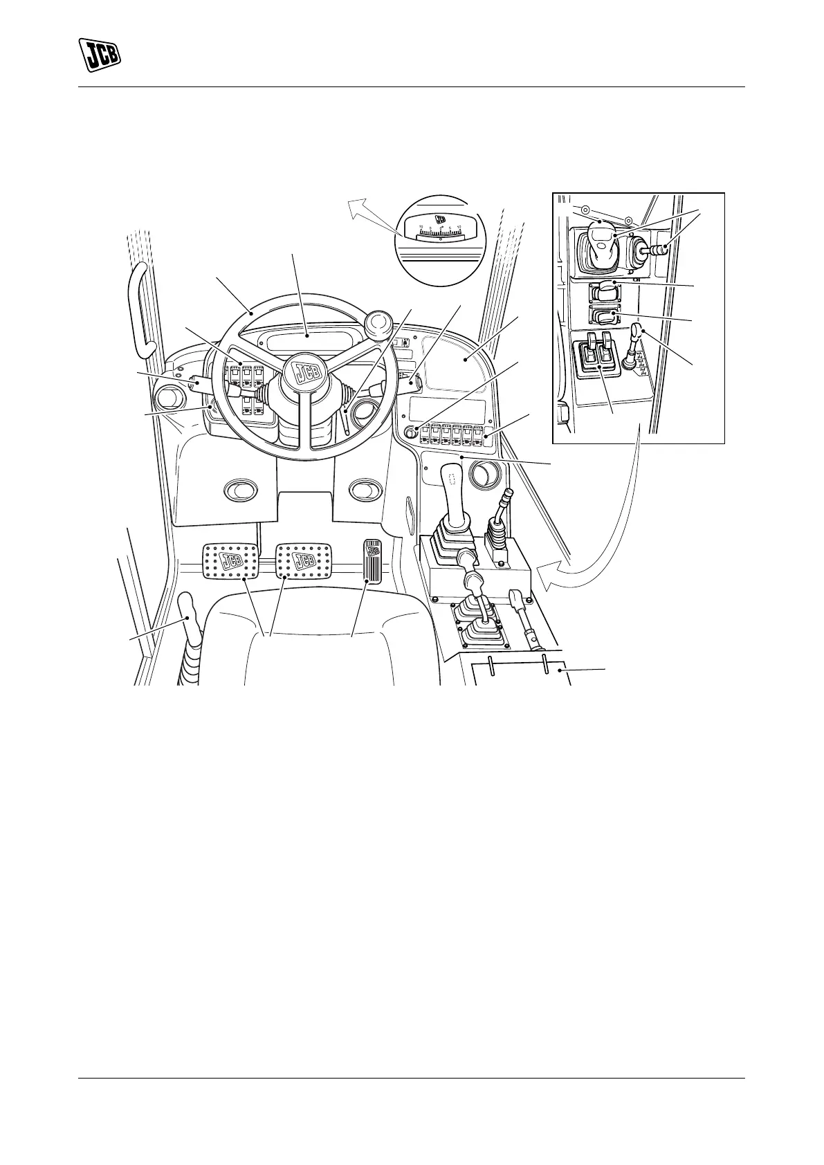
Component Locations
Figure 11.
A Hourmeter Refer to: Instrument Panel
(Page 51).
B Drive lever Refer to: Gear Lever (Page 49).
C Console switches Refer to: Console Switches
(Page 19).
D Steering wheel Refer to: Steering Wheel
(Page 47).
E Instrument panel Refer to: Instrument Panel
(Page 51).
F Steering column adjustment Refer to: Steering
Column (Page 47).
G Multi-purpose switch Refer to: Multi-Purpose
Switch (Page 17).
H Instrument panel Refer to: Instrument Panel
(Page 51).
J Ignition switch Refer to: Ignition Switch
(Page 17).
K Console switches Refer to: Console Switches
(Page 19).
L Load ChartsRefer to: Load Charts
(Page 84).
M Accelerator pedal Refer to: Accelerator Pedal
(Page 47).
N Brake pedals Refer to: Service Brake Pedal
(Page 47).
P Park brake Refer to: Park Brake (Page 48).
Q Boom and carriage controls Refer to: Operating
Levers/Pedals (Page 78).
R Steer mode selectorRefer to: Steer Mode
Control (Page 50).
S Chassis levelling controls Refer to: Operating
Levers/Pedals (Page 78).
T Stabilizer controls Refer to: Operating Levers/
Pedals (Page 78).
U HVAC (Heating Ventilation Air Conditioning)
Refer to: Heating, Ventilating and Air-
Conditioning (HVAC) (Page 101).
V InclinometerRefer to: Inclinometers
(Page 87).
W Auxiliary controlsRefer to: Auxiliary Circuit
Controls (Page 82).
X Transmission dump switchRefer to:
Transmission Dump Switch (Page 49).

 Loading...