About the Product
Operator Station
17 9831/5150-1 17
Operator Station
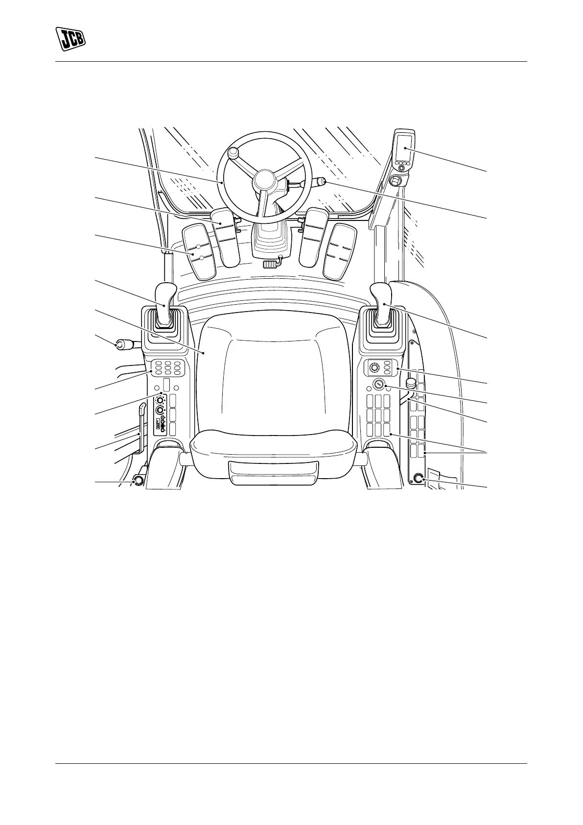
Component Locations
Figure 12.
A TAB (Triple Articulated Boom) pedal, Refer to:
Excavator End Controls (Page 113).
B Auxiliary pedal, Refer to: Auxiliary Circuit
Controls (Page 138).
C Service brake pedalRefer to: Service Brake
Pedal (Page 79).
D Travel pedalRefer to: Accelerator Pedal
(Page 77).
E Steering wheel, Refer to: Steering Wheel
(Page 76).
F Multi purpose steering column switch, Refer to:
Steering Column (Page 77).
G DECU (Display Electronic Control Unit) Refer to:
Instrument Panel (Page 83).
H Right joystick, Refer to: Excavator End Controls
(Page 113).
J Machine power band controller, Refer to:
General (Page 81).
K Ignition switch, Refer to: Ignition Switch
(Page 18).
L Dozer lever, Refer to: Dozer Blade Controls
(Page 137).
M Right switch console, Refer to: General
(Page 21).
N 12 V auxiliary power socket, Refer to: Auxiliary
Power Socket (Page 161).
P Left joystick, Refer to: Excavator End Controls
(Page 113).
Q Seat, Refer to: General (Page 49). R Controls isolation lever, Refer to: Control Lock
(Page 74).
S Left switch console, Refer to: General
(Page 21).
T Door lever, Refer to: Operator Door
(Page 40).
U Wheeled switch panelRefer to: General
(Page 81).

 Loading...