About the Product
Operator Station
16 9821/9300-4 16
Operator Station
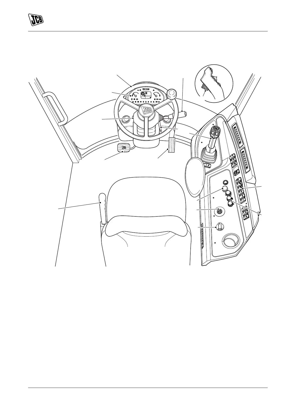
Component Locations
Figure 10.
A Steering wheelRefer to: Steering Wheel
(Page 60).
B Instrument panel Refer to: Instrument Panel
(Page 63).
C Multi-purpose steering column switchRefer to:
Multi-Purpose Switch (Page 18).
D Accelerator pedalRefer to: Accelerator Pedal
(Page 60).
E Forward/reverse switchRefer to: Transmission
Drive Lever (Page 61).
F Transmission drive leverRefer to: Transmission
Drive Lever (Page 61).
G Ignition switchRefer to: Ignition Switch
(Page 18).
H Console switchesRefer to: Console Switches
(Page 21).
J Air conditioning controlsRefer to: Air-
Conditioning Controls (Page 106).
K Rotary throttle control (option)Refer to:
Accelerator Pedal (Page 60).
L Park brakeRefer to: Park Brake (Page 60). M Service brake pedalRefer to: Service Brake
Pedal (Page 60).
N Rotary throttle control (option) Refer to:
Transmission Drive Lever (Page 61).
P Horn
Q Steering column adjustmentRefer to: Steering
Column (Page 60).

 Loading...