CONFIDENTIAL PROPERTY OF JCM GLOBAL DRAFT 5 © 2010, Japan CashMachine Co, Limited
4
iVIZION™ Series Next-Generation Banknote Acceptor Integration Guide
Structural Specifications
This section provides installation and operating
instructions for the iVIZION™ Series Banknote
Acceptor Unit. The information within contains the
following features:
• Installation Process
• DIP Switch Configurations
• Connector Pin Assignments
• Preventive Maintenance
• Clearing Banknote Jam
• Cleaning
• Interface Schematic
• Operational Flowchart
I
NSTALLATION
P
ROCESS
Mounting holes are provided in each Frame Unit to
attach the iVIZION™ to a related Machine during
installation. Select and perform the following steps
to install the iVIZION™ Unit:
1. Install the Interface Harness to the Frame
Grounding Plate (FG PLT) (See Figure 4 a) using
the two (2) Floating Collars (See Figure 4 b), the
single (1) M2.6x12 W Washer (See Figure 4 c),
the single (1) M2.6x10 W Washer (See Figure 4
d) and the single (1) M2.6 Nylon N
ut (See
See Figure 4 e) to the Frame Assembly.
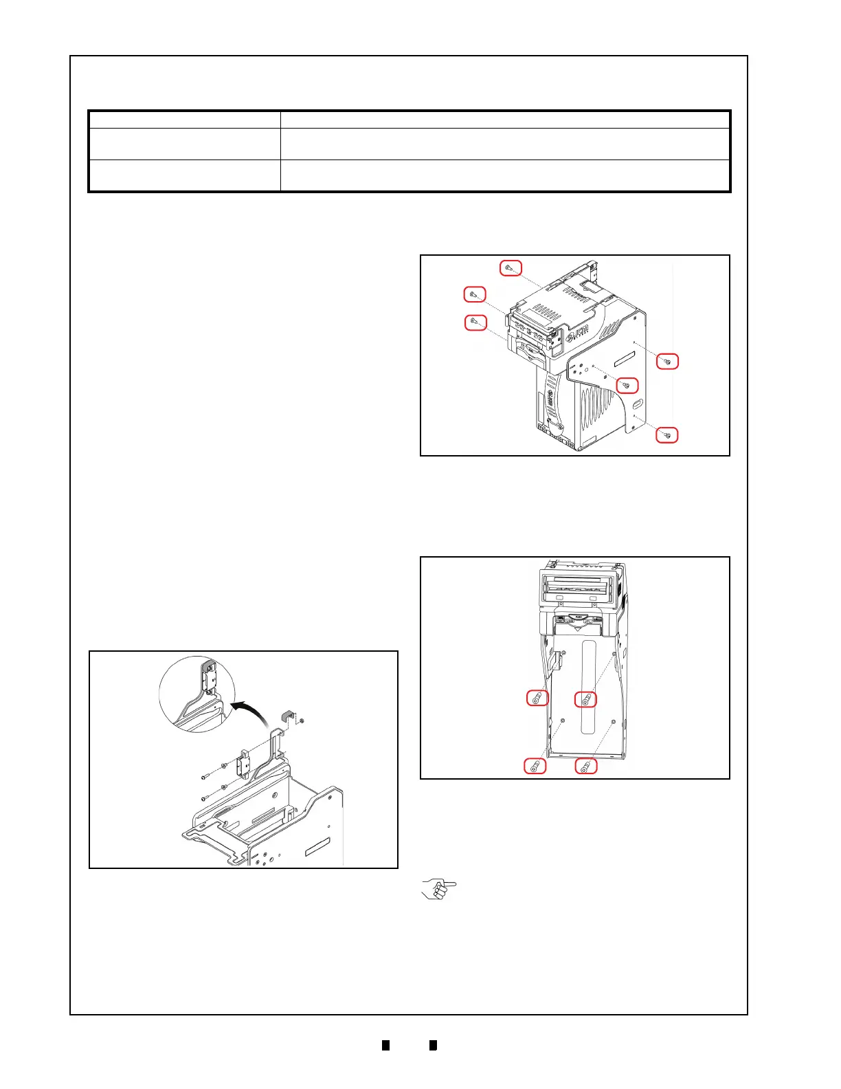
2. When a side mounting configuration is preferred,
bolt the left and right sid
e of the iVIZION™
Frame into its intended location using six (6) M4
Screws on both sides of the Frame (3 Screws on
each side as shown in Figure 4).
3. When an end mounting configuration is preferred,
remove the Cash
Box and bolt the rear end of the
iVIZION™ Frame into its intended location using
four (4) UNC6-32 Flat Head Screws from inside
the back end of the Frame as shown in Figure 5.
When installing the iVIZION™ Unit into the Host
Machine, refer to Figure 12 “iVIZION Instal
lation
and Maintenance Spac
e Requirements Dia
gram”
on page 9 of this document.
Table 4 iVIZION Structural Specifications
Weight Empty: Approximately 4.1kg (9.04 lbs)
Mounting:
Horiz
ontal (Maximum gradient limitation within 50 degrees; See Figure
12 on page 10)
Outside Dimensions:
Refer to “iVIZION Banknote Acceptor Unit Outside Dimensions” on
page 8 of this document.
3 INSTALLATION
Installation Procedure
Figure 3 Interface Harness Installation Location
Figure 4 M4 Screws Locations (Left/Right Side)
Figure 5
Flat Head Screws Locations (Rear Side)
NOTE: The length of the M4 Screws should
be selected in order not to puncture the
Plastic Surface of the iVIZION™ Frame
when aside mounting configuration is
preferred.

 Loading...

