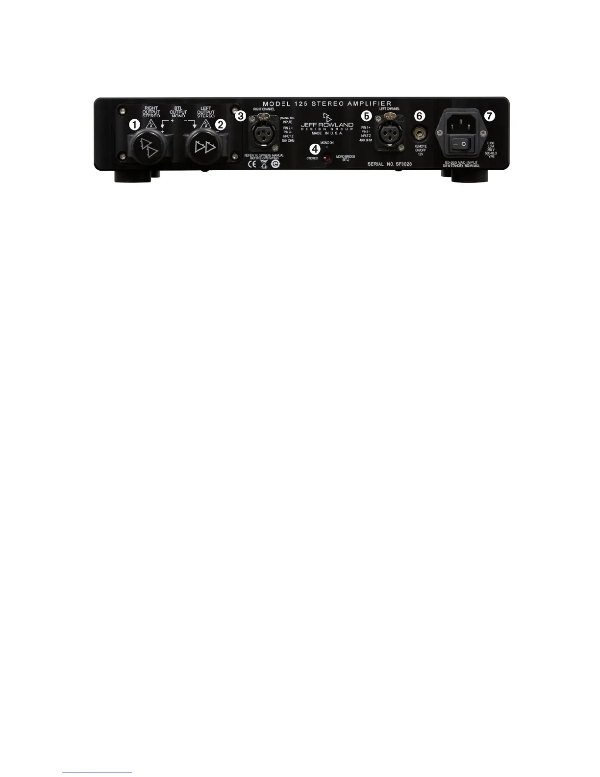
REAR PANEL CONNECTIONS
Figure 2: Rear Panel Connections
1. LOUDSPEAKER OUTPUT. Right Channel.
2. LOUDSPEAKER OUTPUT. Left Channel.
3. INPUT. Right Channel Balanced XLR.
4. BRIDGE MODE SWITCH. Move to the left for STEREO MODE and to the right for BRIDGE MODE.
5. INPUT. Left Channel Balanced XLR.
6. REMOTE ON/OFF. A 1/8” (3.5 mm) mini-plug connector is provided on the rear panel of the MODEL
125 for remotely switching the amplier between Operational and Standby modes. When
connected to another component with the proper circuitry, the amplier standby function can be
turned ON and OFF remotely.
7. AC MAINS INPUT CONNECTOR. Install the AC Power Cable into the AC input connector between
the amplier and your AC mains outlet.
REVA2
MODEL 125 STEREO AMPLIFIER
PAGE 10
 Loading...