17
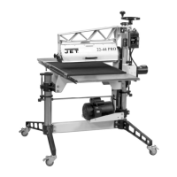
4. If table is not parallel, loosen the four
screws holding the table to the trunnions (B,
Figure 25) with a 12mm wrench, and nudge
the table until parallel. Re-tighten screws.
Note: Always maintain a gap of
approximately 1/16” between the table edge
and the abrasive disc.
Once the table is square and parallel to the disc,
verify the stops, as follows:
Adjust 90° Stop
5. Loosen lock nut on the 90° stop (Figure 23)
with a 10mm wrench. Turn the set screw
down (3mm hex key) to contact the table.
Re-tighten lock nut.
Adjust 45° Stop
6. To adjust the 45° stop, pivot the 90° stop
block out of the way, and tilt the table down
against the 45° stop screw (Figure 25).
Check the angle with a 45° measuring
device on the table and against the disc.
7. If adjustment is necessary, loosen the hex
nut, turn the stop screw as needed, and re-
tighten the hex nut to secure the setting.
Adjust Rear Stop
The rear stop (Figure 26) is used when tilting the
disc table upward. It can be set to limit the table
tilt to about minus 15°. To tilt the table to the full
minus 25°, remove the rear stop screw and nut.
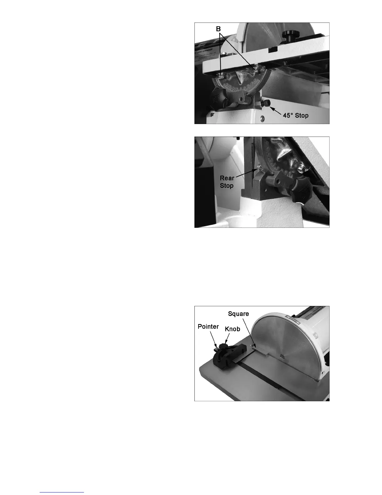
Miter Gauge
Refer to Figure 27.
Check the zero setting of the miter gauge.
(Note: Make sure the miter slot is parallel to the
disc surface.)
1. Place the miter gauge into the disc table slot
and loosen the miter gauge knob.
2. Place a square against miter gauge and
disc so that it sits flush against both
surfaces.
3. Tighten the knob, and check the zero
setting. If necessary, adjust the pointer to
the zero mark.
Figure 25
Figure 26
Figure 27
 Loading...