6 | JL Audio - 1200/1v3 Owner’s Manual
7
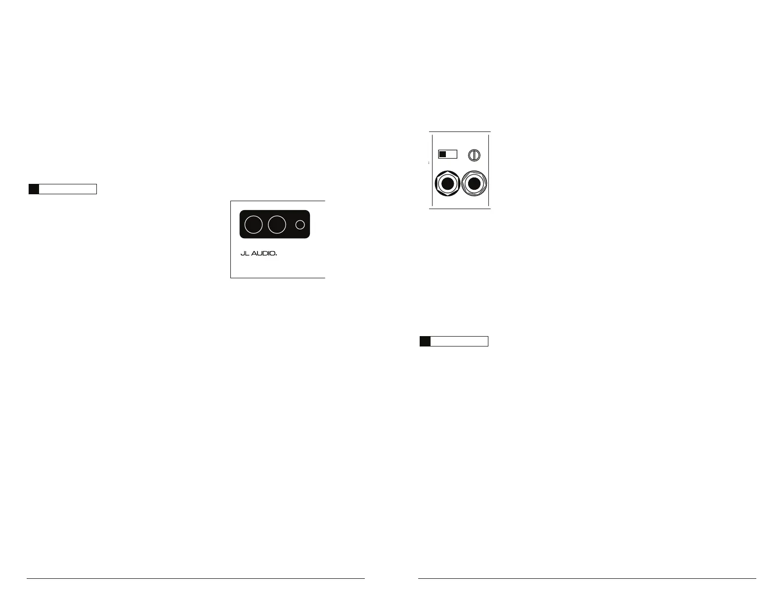
AMPLIFIER INPUT SECTION
The 1200/1v3 employs a differential-balanced
input topology that provides the user with a high
degree of input flexibility while retaining superior
noise rejection. This type of circuit also allows
the 1200/1v3 to accept high-voltage inputs from
factory source unit outputs without excessive
distortion or noise problems.
Amplifier Input Section
Left Ch. Right Ch.
Input Voltage Input Sens.
Low
|
High
1) Input Connections: A standard left/right pair
of RCA type jacks is used for input on
the 1200/1v3. You may run a stereo or a mono
signal into the inputs of the amplifier. The
amplifier’s input section automatically sums
stereo signals to mono for the internal
BNQMJGJFSTFDUJPOBOEGPSUIFiLPwiFilter
ModewPGUIFiPreamp OutputwTFDUJPO
IMPORTANT
!
If you plan to use the “Preamp Output” in
“Full-Range” or “HP” mode to feed a stereo
amplifier, you must connect a stereo signal to
the input of the amplifier. A mono signal into
the amplifier will result in a mono signal out of
the preamp output. (It’s a great amplifier, but it
doesn’t do magic).
The amplifier will operate with only one input
connection (left or right), but will require an
increase in input sensitivity to overcome the loss
of signal. If a mono input signal is to be run, we
SFDPNNFOEUIBUZPVVTFBi:BEBQUPSwMJLFUIF
+-ڀ"VEJP&$4NPEFM9%$-3"*$:'.UPTQMJU
the mono signal into both inputs of the amplifier.
2) Input Voltage Range: A wide range of signal
input voltages can be accommodated by
the 1200/1v3’s input section (200mV – 8V).
This wide range is split up into two sub-
ranges, accessible via switches located in the
iAmplifier Input SectionwPGUIFBNQMJGJFS
5IFiLowwQPTJUJPOPOUIFiInput Voltagew
switch selects an input sensitivity range
between 200mV and 2V. This means that
UIFiInput Sens.wSPUBSZDPOUSPMXJMMPQFSBUF
within that voltage window. If you are using
an aftermarket source unit, with conventional
preamp-level outputs, this is most likely the
QPTJUJPOUIBUZPVXJMMVTF5IFiHighwQPTJUJPO
POUIFiInput VoltagewTXJUDITFMFDUTBOJOQVU
sensitivity range between 800mV and 8V. This
is useful for certain high-output preamp level
signals as well as speaker-level output from
source units and small amplifiers. To use
speaker-level sources, splice the speaker output
wires of the source unit or small amplifier
onto a pair of RCA cables or plugs or use the
JLAudio ECS Speaker Wire to RCA adaptor
9%$-3"*$48
Ground Connection
The chassis ground connection must be made
using 4 AWG pure copper wire and should
be kept as short as possible, while accessing a
solid piece of sheet metal in the vehicle. The
surface of the sheet metal should be sanded at
the contact point to create a clean, metal-to-
metal connection between the chassis and the
termination of the ground wire with a brass or
copper power ring. For optimal grounding, we
recommend the use of a JLAudio master ground
lug (XB-MGLU). Alternatively, a sheet metal
screw or bolt can be used with a star washer.
IMPORTANT
!
Many vehicles employ small (10 AWG - 6 AWG)
wire to ground the battery to the vehicle chassis
and to connect the alternator’s positive
connection to the battery. To prevent voltage
drops, these wires should be upgraded to 4
AWG pure copper wire (or larger) when
installing amplifier systems with main fuse
ratings above 60A.
REMOTE TURN-ON
The 1200/1v3 uses a conventional +12V remote
turn-on lead, typically controlled by the source
unit's remote turn-on output. The amplifier will
turn on when +12V is present at its “Remote”
input and turn off when +12V is switched off. If
a source unit does not have a dedicated remote
turn-on output, the amplifier’s turn-on lead can
be connected to +12V via a switch that derives
power from an ignition-switched circuit.
The 1200/1v3's “Remote” turn-on connector is
designed to accept 12 AWG – 8 AWG wire.
12 AWG is more than adequate for this purpose.
To connect the remote turn-on wire to the
amplifier, first back out the set screw on the
top of the amplifier, using the supplied hex
wrench. Strip 1/2 inch (12mm) of wire and
insert the bare wire into the receptacle on the
front panel of the amplifier, seating it firmly so
that no bare wire is exposed. Smaller wire than
12 AWG can be used, but it may be necessary
to strip 1 inch of insulation from the wire and
fold the bare wire in half prior to insertion.
While holding the wire in the terminal, tighten
the set screw firmly, taking care not to strip
the head of the screw and making sure that
the wire is firmly gripped by the set screw.
+12VDC Ground Remote
12 0 0 /1v3
Monoblock Subwoofer Amplifier
 Loading...