8 | JL Audio - 1200/1v3 Owner’s Manual
9
2) Precise Frequency Selection: The filter
frequency markings on the front panel of
the amplifier are for reference purposes and
are generally accurate to within 1/3 octave
or better. If you would like to select the filter
frequency with a higher level of precision,
consult Appendix C: Chart A-1 (page 16)
of this manual. This chart gives you a more
accurate frequency for each of the forty
detented positions of the frequency selection
control. This method can be very useful if the
amplifier is mounted in a location where you
can’t see the front panel markings easily.
3) Defeating the Amplifier Filter: The Low-
Pass filter can also be defeated completely,
CZTXJUDIJOHUIFiMode/SlopewTXJUDIUPUIF
iOffwQPTJUJPO5IJTJTVTFGVMJGZPVBSFVTJOH
an external active crossover in the system.
Keep in mind that turning the internal
DSPTTPWFSPGGBMTPEFGFBUTUIFiAdvanced Bass
ControlwTFDUJPOQSPDFTTJOHTFFQBHFGPS
details). With the internal crossover turned
off, the 1200/1v3’s upper frequency response
MJNJUJT)[EVFUPJUTCBTTTQFDJGJD
$MBTT%EFTJHO
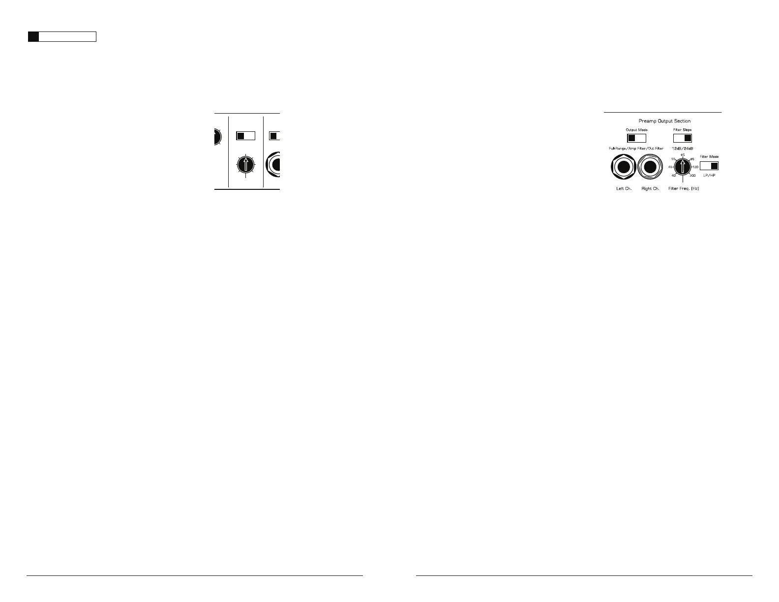
PREAMP OUTPUT SECTION
The 1200/1v3 incorporates a flexible preamp
output section, designed to make multiple
amplifier systems easy to set up.
The Preamp output can be configured in three
EJGGFSFOUiOutput Modesw
1) “Full-Range”: This is a pass-through mode
for the preamp output, delivering the same
TJHOBMUIBUJTCFJOHGFEUPUIFi"NQMJGJFS*OQVU
4FDUJPOw*GUIFJOQVUTJHOBMJTGVMMSBOHFUIF
preamp output will be full-range). This signal is
OPUBGGFDUFECZUIFiAdvanced Bass Controlw
processing selected for the amplifier.
2) “Amp Filter”: The preamp output delivers
the same signal that is feeding the 1200/1v3’s
amplifier section, including all the processing
JOEVDFECZUIFiAmp LP FilterwBOE
iAdvanced Bass ControlwTFDUJPOT5IJT
is primarily used for running additional
WTJOBi4MBWFwDPOGJHVSBUJPOGSPNUIF
i.BTUFSwBNQMJGJFS'PSEFUBJMFEJOGPSNBUJPOPO
i.BTUFS4MBWFwDPOGJHVSBUJPOTTFF"QQFOEJY
%QBHF*GUIFiOutput ModewTXJUDIJT
JOUIFiAmp FilterwQPTJUJPOBOEUIFiAmp
LP FilterwTXJUDIJTJOUIFiOffwQPTJUJPOUIFSF
will be no output from the preamp output
jacks. The independent output filter controls
iFilter SlopewiFilter FreqwBOEiFilter
ModewBSFJOBDUJWFJOiAmp FilterwNPEF
IMPORTANT
!
The output of the amplifier will decrease
for a given input voltage when the “Input
Range” switch is placed in the “High” position.
Conversely, the output will be higher with
the switch in the “Low” position. While this
may sound counter-intuitive, it is correct
as described.
3) Input Sensitivity Adjustment: Located
OFYUUPUIFiInput VoltagewTXJUDIJOUIF
iAmplifier Input SectionwJTBSPUBSZDPOUSPM
MBCFMFEiInput Sens.w0ODFUIFBQQSPQSJBUF
iInput VoltagewSBOHFIBTCFFOTFMFDUFEUIJT
rotary control can be used to match the source
unit’s output voltage to the input stage of the
amplifier for maximum clean output. Rotating
the control clockwise will result in higher
sensitivity (louder for a given input voltage).
Rotating the control counter-clockwise will
result in lower sensitivity (quieter for a given
input voltage). To properly set the amplifier
for maximum clean output, please refer to
Appendix A (page 14) in this manual. After
using this procedure, you can then adjust
the level of the amplifier by adjusting the
input sensitivity downward, if the amplifier
requires attenuation to achieve the desired
TZTUFNCBMBODF%POPUJODSFBTFUIFiInput
Sens.wTFUUJOHGPSBOZBNQMJGJFSJOUIFTZTUFN
beyond the maximum level established during
the procedure outlined in Appendix A (page
%PJOHTPXJMMSFTVMUJOBVEJCMFEJTUPSUJPO
and possible speaker damage.
CROSSOVER CONTROLS
Crossovers are groups of individual electronic
filters which allow only certain frequency
ranges to pass through them by attenuating
frequencies outside the selected range. These
filters allow the user to specify what frequency
range will be sent out of each channel section
of the amplifier. This, in turn, allows each
speaker system to only reproduce a range of
frequencies it is well-suited for, resulting in
reduced distortion and improved fidelity.
AMPLIFIER LOW-PASS FILTER
The 1200/1v3 employs a sophisticated, state-
variable, low-pass active filter for its internal
channel. This feature is designed to attenuate
frequencies above its filter frequency, so that the
system’s subwoofers do not reproduce any audible
midrange content.
(dB)
Amp LP Filter
nced
ol
Left
Filter Freq. (Hz)
Mode
|
Slope
Input V
Off
|
12dB
|
24dB Low
|
40
45
55
65
80
10 0
200
+13
+15
1) Filter Operation: The low-pass filter in the
WJTGVMMZWBSJBCMFCFUXFFO)[BOE
)[WJBUIFiFilter Freq.wDPOUSPMLOPC
and features the ability to select between a
NPEFSBUFi12dBwQFSPDUBWFPSBTUFFQi24dBw
QFSPDUBWFTMPQFWJBUIFiMode/SlopewTXJUDI
%FQFOEJOHPOUIFTVCXPPGFSTZTUFNBOEUIF
vehicle, different slopes may be required to
produce a smooth transition to the mid-bass
speakers in the system. Experiment to find
the slope which best matches the acoustic
requirements of your system.
Tuni ng Hint
: A trunk mounted sub whose output
has to "fight" through a rear deck or a back seat
often benefits from the 12 dB/octave slope which
lets more upper bass content pass through. A sub
that fires directly into the listening environment
is more likely to benefit from a 24 dB/octave slope.
5IFBCPWFIJOUJTOPUiTFUJOTUPOFwy
You should always listen to the system carefully to
determine the best choice as vehicle acoustics and
other factors play a big role in choosing the most
appropriate filter slope.
 Loading...