System 450™ Series Modular Control Systems with Standard Control Modules Technical Bulletin 43
To view the system status screens while the control module LCD is auto-scrolling
through Main screens, press (repeatedly) to scroll through and display the
Sensor Status screens and the Output Status screens for all sensors and outputs set
up in your control system.
When you stop pressing , the Sensor or Output Status screen that is being viewed
is displayed for 2 minutes before it times out and reverts to autoscrolling through
the Main screens. The 2-minute pause allows you to monitor a sensor that is
changing quickly during system setup or operation.
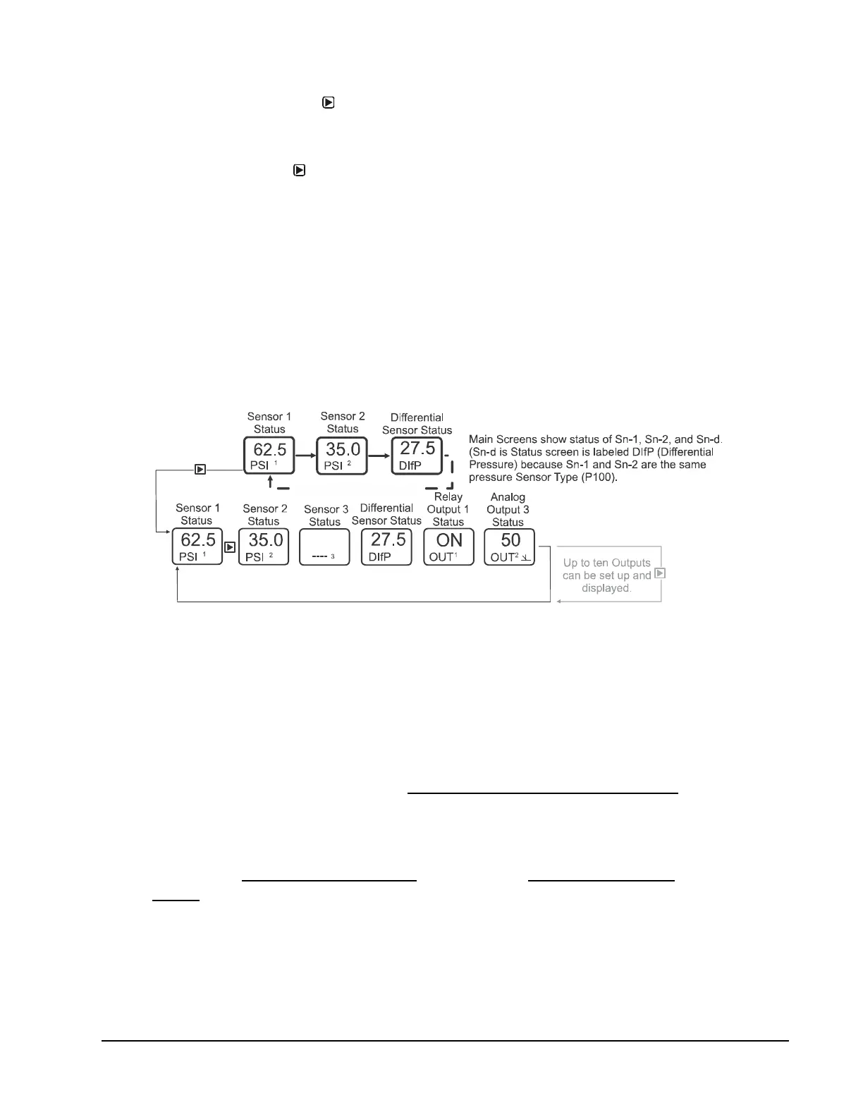
System 450 Main screens display the status at the hard-wired Sn-1, Sn-2, and Sn-3
sensors, and the statuses of the functional sensor Sn-d when used in the control
system. The System Status screens also display hard-wired and functional sensor
statuses along with output statuses.
Figure 17 shows the Main screens (sensor status) and the System Status screens
(sensor and output status) for a standard System 450 control system that is set up
for differential pressure control.
Accessing the System Setup Screens
From the Main screens, you can also access the Sensor Setup Start screen and the
Output Setup Start screens.
• From the Sensor Setup Start screen, you can set up all of the hard-wired
sensors for your control system. (See Setting Up the Sensors and Transducers
on page 45 for procedures on setting up the sensors and transducers, including
functional sensors.)
• From the Output Setup Start screens, you can set up each output in your control
system. (See Setting up a Relay Output
on page 47 and Setting up an Analog
Output on page 50 for procedures on setting up outputs.)
Figure 17: Main Screens and System Status Screens Example for a Standard
System 450 Control System Set Up for Differential Control
Main
Screens
System
Status
Screens
Main Screens Auto-Scroll
FIG:main_and_system_status_screens

 Loading...


