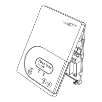
T600HPx-4 and T600HPx-4+PIR Series Heat Pump Thermostat Controllers Installation Instructions20
Technical Specifications
Table 8: Accessories (Order Separately)
Code Number Description
SEN-600-1 Remote Inside Air Temperature Sensor
SEN-600-4 Remote Inside Air Temperature Sensor with Occupancy Override and LED
TE-6361M-1
1
Duct Mount Air Temperature Sensor
TE-636S-1
1
Strap-Mount Temperature Sensor
TE-6363P-1
1
Outside Air Temperature Sensor
TEC-3-PIR
2
Cover with Occupancy Sensor
1. Additional TE-636xx-x Series 10k ohm Johnson Controls Type II Thermistor Sensors are available; refer to the
TE-6300 Series Temperature Sensors Product Bulletin (LIT-216320) for more details.
2. The TEC-3-PIR Accessory Cover can be used to replace the existing cover on a non-PIR T600HPx-4 Series Thermostat
Controller to provide occupancy sensing capability.
Table 9: Display Messages
Display Function
Service Indicates that there is a service alarm in accordance with the programmable Digital Inputs (DI1 or
DI2).
Filter Indicates that the filter(s) is dirty in accordance with the programmable Digital Inputs (DI1 or DI2).
Frost on Indicates that the heating is energized by the low limit frost protection room temperature setpoint.
SetClock Indicates that there has been a power failure greater than 6 hours and the clock needs to be reset
(T600HPP-4 and T600HPP-4+PIR models).
Fan lock Indicates that the thermostat controller heating or cooling action is locked out because no airflow was
detected 10 seconds after the fan (Terminal G) was energized.
T600HPx-4 and T600HPx-4+PIR Series Thermostat Controllers (Part 1 of 2)
Power Requirements 19 to 30 VAC, 50/60 Hz, 2 VA (Terminals RC and C) at 24 VAC Nominal, Class 2 or
Safety Extra-Low Voltage (SELV)
Relay Contact Rating (Y2, Y1, G, W1,
O/B, and AUX)
30 VAC, 1.0 A Maximum, 3.0 A Inrush, Class 2 or SELV
Digital Inputs Voltage-Free Contacts across Terminal C to Terminals DI1 and DI2
Wire Size 18 AWG (1.0 mm Diameter) Maximum, 22 AWG (0.6 mm Diameter) Recommended
Temperature Sensor Type Local 10k ohm Johnson Controls Type II Negative Temperature Coefficient (NTC)
Thermistor Sensor
Temperature Range Backlit
Display
-40.0°F/-40.0°C to 122.0°F/ 50.0°C in 0.5° Increments
Heating
Control
40.0°F/4.5°C to 90.0°F/32.0°C
Cooling
Control
54.0°F/12.0°C to 100.0°F/38.0°C
Accuracy Temperature ±0.9F°/±0.5C° at 70.0°F/21.0°C Typical Calibrated
Minimum Deadband 2F°/1C° between Heating and Cooling
Ambient Conditions Operating 32 to 122°F (0 to 50°C); 95% RH Maximum, Noncondensing
Storage -22 to 122°F (-30 to 50°C); 95% RH Maximum, Noncondensing

 Loading...