EasyManuals Logo
Home>Johnson Controls>Thermostat>T9500

Johnson Controls T9500 User Manual

Johnson Controls T9500
100 pages
To Next Page IconTo Next Page
To Previous Page IconTo Previous Page
Page #81 background imageLoading...
Page #81 background image
74
Installation Instructions
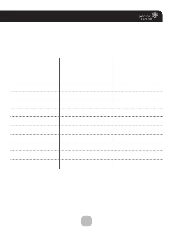
Wire Connections
If the terminal designations on your old thermostat do not match those
on the new thermostat,
refer to the chart below or the wiring
diagrams that follow.
Wire from the Install on the
old thermostat Function new thermostat
terminal marked connector marked
G or F Fan G
Y1, Y Cooling Y1
W1, W Heating W1/0/B
Rh, R, M, Vr, A Power R
C Common C
O/B Rev. Valve W1/O/B*
W2 2nd Stage Heat W2
Y2 2nd Stage Cooling Y2
W3 3rd Stage Heat W3
OUT - Outdoor Sensor SENSOR
OUT + Outdoor Sensor SENSOR
* O/B is used if your system is a Heat Pump.

Table of Contents

Questions and Answers:

Question and Answer IconNeed help?

Do you have a question about the Johnson Controls T9500 and is the answer not in the manual?

Johnson Controls T9500 Specifications

General IconGeneral
BrandJohnson Controls
ModelT9500
CategoryThermostat
LanguageEnglish

Related product manuals