TEC3000 Series Networked and Wireless Proportional Fan Coil and Individual Zone Thermostat Controllers with
Dehumidification Capability Quick Start Guide
30
Repair Information
If the TEC3000 Series Thermostat Controller fails to operate within its specifications, replace the unit. For a
replacement thermostat controller, contact the nearest Johnson Controls representative.
Technical specifications
For wireless models, Supervisory
Status = Offline
The supervisory controller is not
communicating with the TEC.
The TEC is not mapped to a JCI
Supervisory System. The WNC
Gateway is not communicating
with the TEC.
1. Map the TEC into a JCI Supervisory system.
2. Verify that the PAN’s WNC Gateway is online.
3. Add ZFR Pro Routers/Repeaters into the
wireless system.
Some icons are hidden. Lockout levels are used or the
icons are hidden due to the
display settings.
See Table 4 for lockout levels and access details.
The touchscreen is unresponsive. You tap the display or touch the
controller within 5 mm of the
display when power is applied to
the controller.
Reboot the controller. Do not interact with the
controller until the home screen displays.
You do not tap the touchscreen, but
the display acts as if it is tapped,
which causes the display to blink or
toggle between screens.
You need to tap the display at an
offset from a touch point to activate
the display.
1. For common MS/TP troubleshooting information, refer to the MS/TP Communications Bus Technical Bulletin
(LIT-12011034).
TEC3000 Series Networked And Wireless Proportional Fan Coil And Individual Zone Thermostat
Controllers With Dehumidification Capability (Part 1 of 2 )
Power requirements 19 to 30 VAC, 50/60 Hz, 4 VA at 24 VAC nominal, Class 2 or
safety extra-low voltage (SELV)
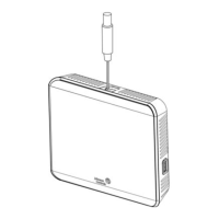
USB port power rating 120 to 250 mA current draw supported
Analog output rating 0 to 10 VDC into 2k ohm resistance (minimum)
Fan relay output rating 19 to 30 VAC, 1.0 A maximum, 15 mA minimum, 3.0 A in-rush
Auxiliary output rating/triac
output
19 to 30 VAC, 1.0 A maximum, 15 mA minimum, 3.0 A in-rush
Binary inputs Dry contact across terminal COM to terminals BI1, BI2, or COS
Analog inputs Nickel, platinum, A99B, 2.25k ohm NTC, 10k ohm NTC, 10k ohm NTC Type 3 across
terminal COM to terminals R SEN or COS
Temperature sensor type Local digital sensor
Wire size 18 AWG (1.0 mm diameter) maximum, 22 AWG (0.6 mm diameter) recommended
MS/TP network guidelines For wired models: Up to 100 devices maximum for each Network Automation Engine
(NAE); 4,000 ft (1,219 m) maximum cable length. Refer to the MS/TP Technical
Bulletin for the Metasys, FX, or Verasys® system installed.
For wireless models: Up to 100 devices maximum for each Network Automation
Engine (NAE)
Wireless band (for wireless
models)
Direct-sequence spread-spectrum 2.4 GHz ISM bands
Transmission power (for wireless
models)
10 mW maximum
Table 8: Troubleshooting details
1
(Part 3 of 3)
Symptom Probable causes Solutions

 Loading...