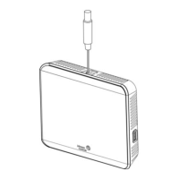
devices on the FC Bus and N2 Bus, set the EOL
switch to the ON position. See Figure 5.
Figure 5: EOL switch position (left) and installing the
thermostat controller cover (right)
5. Reattach the thermostat controller cover to the
mounting base, bottom side first.
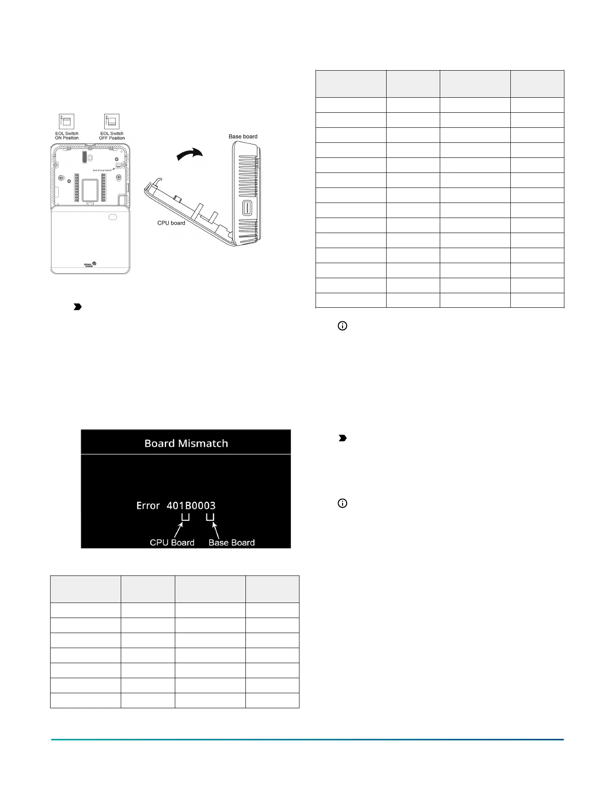
Important: Make sure you reattach the cover
that corresponds to its correct base. The CPU
board number needs to match the base board
number. Otherwise, an operation error occurs
after you reattach a cover and base that do
not belong together. The example in Figure
6 indicates that a TEC3612-16 CPU board is
mounted on the base of a TEC3312-16. See the
following table for TEC3000 model names and
code numbers.
Figure 6: Error code indicating mismatched boards
Table 4: TEC3000 model names and code numbers
Name Code
number
Name Code
number
TEC3012-13 30 TEC3313-14 05
TEC3012-14 31 TEC3322-13 08
TEC3012-16 33 TEC3322-14 09
TEC3013-14 35 TEC3322-16 0B
TEC3022-13 38 TEC3323-14 0D
TEC3022-14 39 TEC3330-13 10
TEC3022-16 3B TEC3330-14 11
Table 4: TEC3000 model names and code numbers
Name Code
number
Name Code
number
TEC3023-14 3D TEC3330-16 13
TEC3030-13 40 TEC3331-14 15
TEC3030-14 41 TEC3612-13 18
TEC3030-16 43 TEC3612-14 19
TEC3031-14 45 TEC3612-16 1B
TEC3112-14 49 TEC3613-14 1D
TEC3113-14 4D TEC3622-13 20
TEC3122-14 51 TEC3622-14 21
TEC3123-14 55 TEC3622-16 23
TEC3130-14 59 TEC3623-14 25
TEC3131-14 5D TEC3630-13 28
TEC3312-13 00 TEC3630-14 29
TEC3312-14 01 TEC3630-16 2B
TEC3312-16 03 TEC3631-14 2D
Note: The two-character code number is listed
within the error code to indicate that the CPU
board and base board do not belong together.
6. Use a 1/16 in. (1.5 mm) Allen wrench or Johnson
Controls T-4000-119 Allen-Head Adjustment Tool
(order separately) to reinstall the security screw
on the top of the thermostat controller cover. See
Figure 2 for security screw placement.
7. Remove the protective plastic cover sheet from the
display.
Important: If the display is dirty, gently wipe
it clean with isopropyl alcohol or ethyl alcohol.
Do not scrub hard as to avoid damaging the
surface. Do not use other cleaners such as
water, ketones, and aromatic solvents, since
they may damage the polarizer.
Note:
- For VAV and two-pipe systems, connect
the valve to the heating output.
- Only one transformer is required for each
TEC.
- Power to the AUX contact comes from
the reheat coil.
See Wiring diagrams for wiring diagrams. See
Table 5 for terminal identification.
TEC3000 Series Proportional Fan Coil Thermostats Installation Guide 5
 Loading...