Home
JUKI
Sewing Machine
DDL-9000B-SH
JUKI DDL-9000B-SH User Manual
5
of 1
of 1 rating
113 pages
Give review
Manual
Specs
To Next Page
To Next Page
To Previous Page
To Previous Page
Loading...
– 40 –
(10)
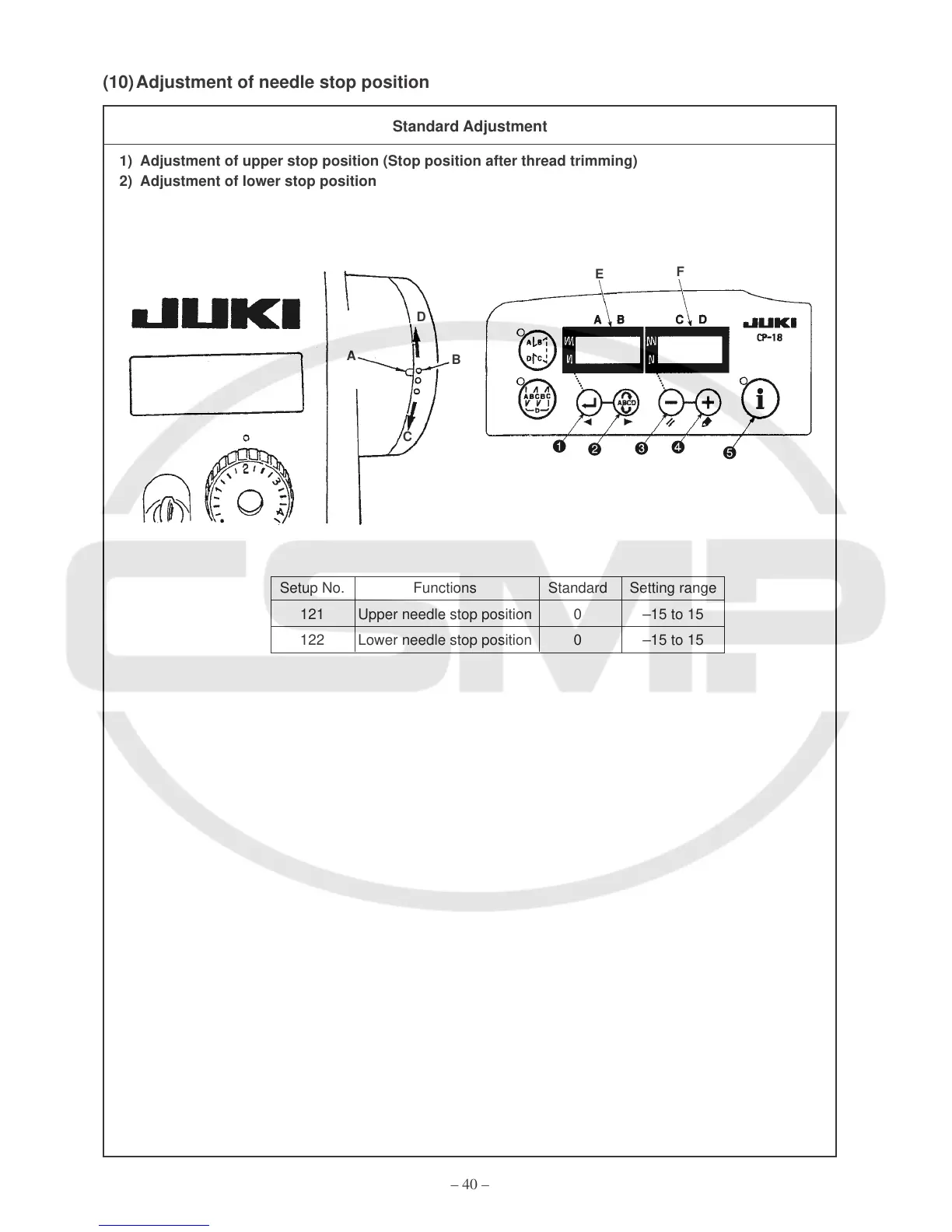
Adjustment of needle stop position
1)
Adjustment of upper stop position (Stop position after thread trimming)
2)
Adjustment of lower stop position
B
A
C
D
Standard Adjustment
Setup No.
Functions
Standard
Setting range
121
Upper needle stop position
0
–15 to 15
122
Lower needle stop position
0
–15 to 15
E
F
43
45
Table of Contents
Default Chapter
3
Table of Contents
3
Specifications
5
Name of each Component
6
Standard Adjustment
8
Feed Dog Height and Gradient
8
Timing for the Needle and the Inner Hook
10
Needle and Feed Timing
12
Feed Locus and Phase
14
Bobbin Insertion
16
Bobbin Case with Idling Prevention Spring
16
Adjustment of Inner Hook Presser Position
18
Lubrication
20
Method of Lubrication
20
Method of Lubrication to the Oil Tank
22
Method of Oil Drainage from the Oil Tank
22
Cleaning of the Oil Filter
24
Oil in the Gear Box
26
Placement/Displacement of the Gear Box Cover
26
Cautions for Gear Box Cover Oil During Transportation
26
Adjustment of Hook Oil Quantity
28
Hook Oil Adjustment Procedures
28
Essentials for Hook Oil Adjustments
28
Replacement of the Hook Shaft Oil Wick
28
Adjustment of the Amount of Feeding
30
Adjustment of Forward Feed Stitch Length
30
Adjustment of Reverse Feed Stitch Length (Manual)
30
Adjustment of Reverse Feed Stitch Length (Motor-Power)
30
Optional Switch
32
Adjustment of Normal/Reverse Stitching
34
Adjustment of Feed 0
34
Method by Removing the Gear Box Cover (Standard Adjustment)
34
Adjustment of the Feed Dial Section
36
Installation of the Reverse Feed Arm and the Reverse Feed Solenoid
38
Stop Position of the Feed Control Spring Rack
38
Adjustment of the Presser Lifter
40
Adjustment of the Presser Pressure
40
Adjustment of Thread Release Changeover
40
Adjustment of the Micro-Lifter
42
Adjustment of the Micro-Lifter Unit (Available Separately)
42
Adjustment of Needle Stop Position
44
Adjustment of Upper Stop Position (Stop Position after Thread Trimming)
44
Adjustment of Lower Stop Position
44
Thread Trimming Unit
46
Adjustment of the Thread Trimming Cam Position
46
Adjustment of the Thread Trimming Link Stopper Screw
46
Standard Timing for the Thread Trimming Cam
48
Method of Confirmation
49
Method of Adjustment
49
Correct Position of the Moving Knife
50
Extreme Backward Position
51
Initial Position
51
Correct Position of the Counter Knife
52
Adjustment of Rise of the Second Thread Tension Disc
54
How to Check the Amount of Rise of the Second Thread Tension Disc
55
How to Adjust the Amount of Rise of the Second Thread Tension Disc
55
Adjustment of the Fixed Knife Blade Tip
56
Replacement of the Moving Knife
58
Replacement of the Knife Thread Guide
60
Adjustment of the Picker
62
Method of Confirmation
63
Method of Standard Adjustments (Adjustment of Clearance)
63
Method of Standard Adjustments (Adjustment of Tip Position)
63
Adjustment of the Drive Part Stopper
64
Replacement of the Knife Unit
66
Installed Length of the Thread Trimmer Connector Bar (Asm.)
66
Protrusion of the Thread Trimming Shaft and Stopper Position
68
Adjustment of the Wiper (DDL-9000B- -WB)
70
Adjustment of the Thrust Values for the Upper Shaft and the Upper/Lower Feed Shafts
72
Adjustment of External Parts
74
Adjustment of the Pulley Cover
74
Clearance of the Hand Wheel
74
Adjustment of the Bobbin Winder Unit
76
Replacement of the Bobbin Friction Wheel
77
Adjustment of the Bobbin Winder Driver Wheel Position
77
Maintenance
78
Oil Quantity Check
78
Cleaning
78
Application of Appropriate Grease
78
Needle Bar Lower Bushing (DDL-9000B-M , B-DS Specification)
78
Feed Bar Mechanisms
80
Face Plate Mechanism
82
Lubrication Mechanism Configuration and Adjustments (DDL-9000B-SS, SH, MA, MS)
84
Thread Take-Up Lever Mechanism
86
Replacement of the Motor
88
Replacement of the Timing Belt
88
Screws for Attachment and Positions of External Parts
90
Dry Hook
91
Cautions When a Dry Hook Is Used
91
Replacement of the Dry Hook
91
Head Section and Control Circuit Connection Diagram
92
Air Blow Type Hook Cooling Unit (Available Separately)
93
Troubles and Corrective Measures
94
Mechanical Parts
94
Sewing Conditions
100
Drawing of the Table
111
5
Based on 1 rating
Ask a question
Give review
Questions and Answers:
Need help?
Do you have a question about the JUKI DDL-9000B-SH and is the answer not in the manual?
Ask a question
JUKI DDL-9000B-SH Specifications
General
Brand
JUKI
Model
DDL-9000B-SH
Category
Sewing Machine
Language
English
Related product manuals
JUKI DDL-9000B-SS
16 pages
JUKI DDL-9000B
26 pages
JUKI DDL-9000B-DS
16 pages
JUKI DDL-9000B-MS
16 pages
JUKI DDL-9000
46 pages
JUKI DDL-9000A
79 pages
JUKI DDL-9000C-S
113 pages
JUKI DDL-9000C-F
138 pages
JUKI DDL-9000C-SMS
198 pages
JUKI DDL-9000C-FMS
198 pages
JUKI DDL-9000C-S Series
198 pages
JUKI DDL-900A
52 pages

 Loading...