Operation manualⅠ
S-2
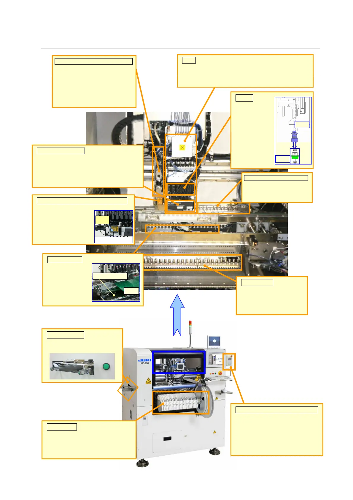
Description
Head
This device picks up, centers and places a component.
The machine is equipped with four “LNC60 heads”
(Z axis: 6 pieces)
Offset Correction Camera (OCC)
This is a camera that checks a
mark and/or component placement
coordinates on a board and/or
adjusts the mark or component
placement position.
This is also provided with a bad mark
sensor function.
LNC60 (Laser unit)
This is a laser unit that finds
the center of a component
(centers a component). (It
can center six components
at the same time.)
Nozzle
This is a unit that
is to be attached
on the tip of the
head (LNC60) to
pick up a
component.
Head
Nozzle
uto Tool Change
(ATC)
This is a unit that stores
nozzles.
Height Measurement System (HMS)
This is a sensor that
measures the height of
a board or a component
mainly.
(Option)
HMS
Support table
This table is used to
support the PWB.
Using support pins
can improve the
stability.
Support table
Board
Feeder bank
This is the base on which a
component supplying
device such as a tape
feeder is to be attached on.
Tape feeder
This is a component supplying device
that supplies chip components or othe
type of components to be placed on a
board.
Handheld Operating Device (HOD)
This is an operation panel for
performing operations such as
adjustment of the component
placement coordinates on a board
(teaching) with each unit (such as an
OCC).
Conveyor LED
When the LED is ON, it is
available to load/unload a PWB
.