41.
AUTOMATIC
PRESSER
FOOT
LIFTER,
AK-II
(optional
attachment)
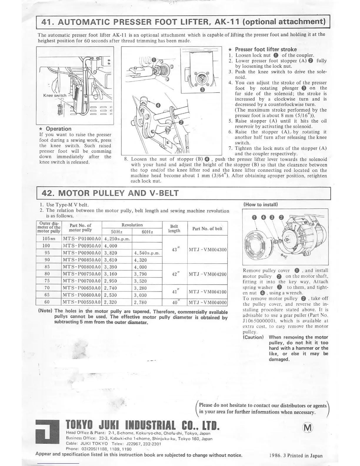
The automatic
presser
foot lifter
AK-11
is an optional attachment which is capableof lifting the presser foot and holdingit at the
heighest
position
for
60
seconds
after
thread
trimming
has
been
made.
I I
—I
*
Presser
foot
lifter
stroke
^ .. . 1.
Loosen
locknut O of the
coupler.
\ n * ~ — 2.
Lower
presser
foot stopper (A)0
fully
.—..
•—
J^i
cU
by
loosening
the
lock
nut.
' l' I 3.
Push
the
knee
switch
to
drive
the
sole-
-
f^l
''
adjust
the
stroke
of
the
presser
•(7 ^
rotating
plunger
@ on the
Knee
switch
—
•/
n\
solenoid;
the
stroke
is
n ^ ^ ^ \ \
increased
by
a
clockwise
turn
and
is
l L=
<=
c V /r^ 1
decreased
by
a
counterlockwise
turn.
Ml
J/^
(The
maximum
stroke
performed
by
the
^1
<=r-<5y
-=.
<=
<=
/^
\(^)
presser
foot
is
about
8
mm
(5/16")).
n(i
(W
^ 5.
Raise
stopper
(A)
until
it
hits
the oil
*
Operation
^[dLfM\
K ^
reservoir
by
activating
the
solenoid
If
.
\\
I
lU
W V o-
Raise
the
stopper
(A),
by
rotating
it
If
you
want
to
raise
the
presser
/ri\
rn »u u
ir..
f- i • »u i
r \ . • • ,
Nv
1
another
half
turn
after
releasing
the
knee
foot
during
a
sewing
work,
press
I®\S4\ 1
switch
the knee switch. Such
raised
\\
W i
t'
u*
'
♦!.
i i *
<•
*i.
♦
/•a\
. ^ .
\\
w\\p
7.
Tighten
the
lock
nuts
of
the
stopper
(A)
presser
foot
will
be
comming
\\
/^iWb
j
.v
i »• .
^ . j- » 1 ft th ' - ^ I and the
coupler
respectively.
own la e y a er e g loosen the nut of
stopper
(B) O >
push
the
presser
lifter
lever
towards
the
solenoid
nee
swi
c isre
ease
.
your
hand
and
adjust
the
height
of the
stopper
(B)
so
that the
clearance
between
the
top
end/of
the
knee
lifter
rod
and
the
knee
lifter
connecting
rod
located
on
the
machine
head
becomeabout 1 mm (3/64"). After obtaining aproper position, retighten
each
lock
nut.
*
Operation
If
you
want
to
raise
the
presser
foot
during
a
sewing
work,
press
the
knee
switch.
Such
raised
presser
foot
will be
comming
down
immediately
after
the
knee
switch
is
released.
42.
MOTOR
PULLEY
AND
V-BELT
1. Use
Type-M
V
belt.
2.
The
relation
between
the
motor
pully, belt length
and
sewing machine revolution
is
as
follows.
Outer
dia
meter
of
the
motor
pully,
Part
No.
of
motor
pully
Revolution
MTS-POIOOOAO
4,250s.p.m.l
MTS-P00950AO
4,000
3,820 I
4.540s.p.m.
MTS-P00850AO 3,610 4,320
MTS-P00800A0 3,390 4,000
MTS-POQ750A0
3.160 3,790
MTS-P00700A0 2,950 3.520
MTS-P00650A0
2,740
3,280
MTS-P00600A0
2,530
3,030
MTS-P00550A0
2.320 2,780
Part
No.
of
belt
MTJ
-VM004300
ImTJ
-VM004200
;MTJ
-VM004100
I
MTJ
-VM004000
(Note)
The
holes
in
the
motor
pully
are
tapered.
Therefore,
commercially
available
pullys
cannot
be
used.
The
effective
motor
pully
diameter
Is
obtained
by
subtracting
5
mm
from
tbe
outer
diameter.
-c-
f
(How
to
Install)
O O 0 0
Remove pulley cover O . and install
motor
pulley 0 on the
motor
shaft,
fitting
it
into
the
key way.
Attach
spring washer 0 to them, and tight
en
nut
O , using a wrench.
To remove motor pulley 0 . take off
the pulley cover, and reverse
the
in
stalling
procedure
stated
above. It is
advisable to use a gear puller
(Part
No.
J1065000000),
which
is
available
at
extra
cost,
to
easy
remove
the
motor
pulley,
(Caution)
When
removing
the
motor
pulley,
do
not
hit
It
too
hard
with
a
hammer
or
the
like,
or
else
it
may
be
damaged.
Please
do not hesitate to contact our distributorsor
agents
inyour area for further informations when
necessary.
•
TOKYO
JUKI
IKOUSTRIAl
CO..
ITO.
Head Office & Plant: 2-1, 8-chome, Kokuryo-cho, Chofu-shi, Tokyo, Japan
Business Office: 23-3, Kabuki-cho 1<home, Shinjuku-ku. Tokyo 160, Japan
Cable:
JUKI
TOKYO
Telex:
J22967,
232-2301
Phone:
03(205)1188,1189,1190
Appear
and
specification
listed
in
this
instruction
book
are
subjected
to
change
without
notice.
1986.
3
Printed
in
Japan
 Loading...