2.
LUBRICATION
5
'L"
mark
j
*H"mark
Oil reservoir
Oilsightwindow^
•k
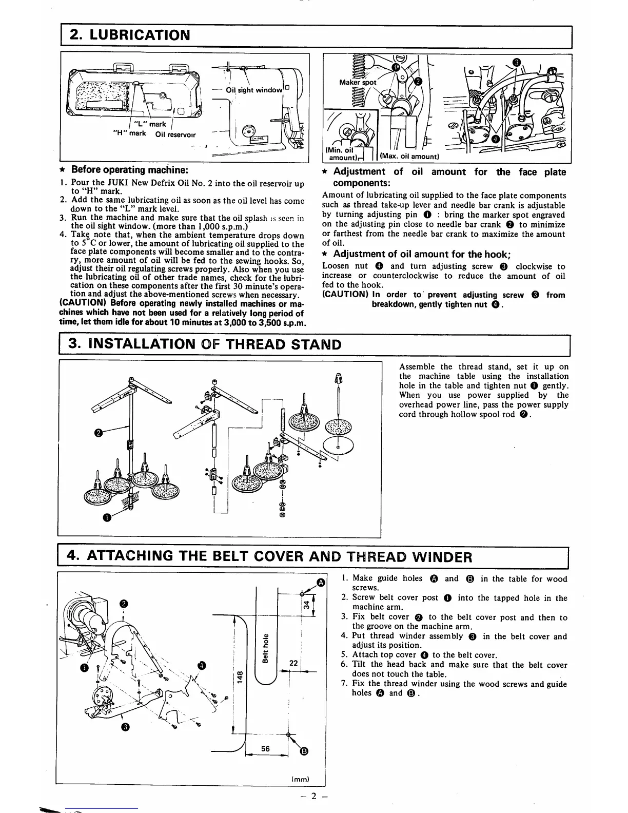
Before operating machine:
1. Pour the JUKI New Defrix Oil No. 2 into the oil reservoir up
to
"H"
mark.
2.
Add
the
same
lubricating oil as
soon
as
the
oil level has
come
down
to
the
"L"
mark
level.
3. Run
the
machine and make sure
that
the
oil splash is seen in
the
oil sight window, (more
than
1,000 s.p.m.)
4. Take note that, when the ambient temperature drops down
to 5 C or lower, the amount of lubricating oil supplied to the
face
plate
components
will
become
smaller
and
to
the
contra
ry, more amount of oil will be fed to
the
sewing hooks. So,
adjust their oil regulating screwsproperly. Also when you use
the
lubricating oil
of
other
trade names, check for
the
lubri
cation on these components after the first 30 minute's opera
tion and adjust the above-mentioned screws when necessary.
(CAUTION) Before operating newly Installed machines or ma
chines which have not been used for a relatively long period of
time, let them idle for about 10 minutes at 3,000 to 3,500 s.p.m.
Maker
spot
(Min.
oil
amount)
(Max. oil
amount)
*
Adjustment
of
oil
amount
for
the
face
plate
components:
Amount
of
lubricating oil supplied to
the
face plate
components
such a£
thread
take-up lever and needle bar
crank
is adjustable
by turning adjusting pin O : bring
the
marker
spot
engraved
on
the
adjusting
pin
close
to
needle
bar
crank
0
to
minimize
or
farthest
from
the
needle
bar
crank
to
maximize
the
amount
of
oil.
★
Adjustment
of
oil
amount
for
the
hook;
Loosen
nut
O and
turn
adjusting screw 0 clockwise to
increase
or
counterclockwise
to
reduce
the
amount
of
oil
fed
to
the
hook.
(CAUTION) In order
to'
prevent adjusting screw 0 from
breakdown,
gently
tighten
nut
O.
3.
INSTALLATION
OF
THREAD
STAND
Assemble
the
thread
stand,
set
it
up
on
the
machine
table
using
the
installation
hole in the table
and
tighten
nut
O gently.
When
you
use
power
supplied
by
the
overhead
power
line,
pass
the
power
supply
cord
through hollow spool rod
0.
CD
4.
ATTACHING
THE
BELT
COVER
<0:
<
(mm)
- 2 -
THREAD
WINDER
1. Make guide holes ®
and
© in the table for
wood
screws.
2. Screw belt cover
post
O
into
the
tapped
hole in
the
machine
arm.
3. Fix belt cover 0 to the
belt
cover
post
and
then
to
the
groove
on
the
machine
arm.
4.
Put
thread
winder
assembly 0 in
the
belt
cover
and
adjust
its
position.
5.
Attach
top
cover
O to
the
belt
cover.
6.
Tilt
the
head
back
and
make
sure
that
the
belt
cover
does
not
touch
the
table.
7. Fix the thread winder using the wood screws and guide
holes © and
©.
 Loading...