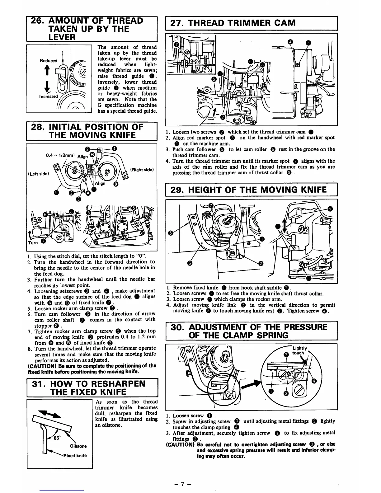
26.
AMOUNT
OF
THREAD
TAKEN
UP
BY
THE
LEVER
Reduced
Increased
The
amount
of
thread
taken
up
by
the
thread
take-up
lever
must
be
reduced
when
light
weight
fabrics
are
sewn;
raise thread guide
O.
Inversely,
lower
thread
guide O
when
medium
or
heavy-weight
fabrics
are
sewn.
Note
that
the
G
specification
machine
has
a
special
thread
guide.
28.
INITIAL
POSITION
OF
THE
MOVING
KNIFE
0.4 ~
Aii„„
©
(Left
side)
Align 0
o
(Right
side)
1. Using
the
stitch
dial, set
the
stitch length to
"0".
2.
Turn
the
handwheel
in
the
forward
direction
to
bring
the
needle to
the
center
of
the
needle hole in
the
feed
dog.
3.
Further
turn
the
handwheel
until
the
needle
bar
reaches
its
lowest
point.
4. Loosening setscrews o and O , make adjustment
so that the edge surface of the feed dog O aligns
with O and 0 of fixed knife © .
5. Loosen rocker arm clamp screw 0 .
6.
Turn
cam follower 0 in
the
direction
of
arrow
cam roller shaft 0 comes in
the
contact with
stopper 0 .
7. Tighten rocker arm clamp screw 0 when the top
end
of
moving knife 0 protrudes
0.4
to 1.2 mm
from
O and ©
of
fixed
knife
0 .
8.
Turn
the
handwheel,
let
the
thread
trimmer
operate
several
times
and
make
sure
that
the
moving
knife
performas its
action
as adjusted.
(CAUTION) Be sure
to
complete
the
positioning of
the
fixed knife
before
positioning
the
moving knife.
31.
HOW
TO
RESHARPEN
THE
FIXED
KNIFE
Oilstone
Fixed
knife
As
soon
as
the
thread
trimmer
knife
becomes
dull, resharpen
the
fixed
knife
as
illustrated
using
an
oUstone.
27.
THREAD
TRIMMER
CAM
1.
Loosen
two
screws
0
which
set
the
thread
trimmer
cam
O
2. Align
red
marker
spot
0
on
the
handwheel
with
red
marker
spot
O
on
the
machine
arm.
3.
Push
cam
follower 0
to
let
cam
roller
0 rest
in
the
groove
on
the
thread
trimmer
cam.
4.
Turn
the
thread
trimmer
cam
until
its
marker
spot
0 aligns
with
the
axis
of
the
cam
roller
and
fix
the
thread
trimmer
cam
as
you
are
pressing
the
thread trimmer cam
of
thrust collar 0 .
29.
HEIGHT
OF
THE
MOVING
KNIFE
1
^0r
✓WiSU/1
P
® \ \ ^
0
1.
Remove
ftxed
knife
O
from
hook
shaft
saddle
0.
2.
Loosen
screws 0
to
set
free
the
moving
knife
shaft
thrust
collar.
3.
Loosen
screw O
which
clamps
the
rocker
arm.
4. Adjust moving knife
link
0 in
the
vertical direction
to
permit
moving knife 0 to
touch
moving knife rest
0.
Tighten screw
0.
30.
ADJUSTMENT
OF
THE
PRESSURE
OF
THE
CLAMP
SPRING
Lightly
0
touch
1. Loosen screw O .
2. Screw in adjusting screw 0 until adjusting metal fittings 0 lightly
touches the clamp spring O
3. After adjustment, securely tighten screw O to fix adjusting metal
nttings
0 .
(CAUTION)
Be careful not to overtighten adjusting screw 0 , or else
and
excessive spring pressure will result and inferior
damp
ing
may
often
occur.
- 7 -
 Loading...