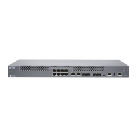
4. Dress the grounding cable and verify that it doesn't touch or block access to router components, or drape where
people could trip over it.
5. Ensure that the power supplies are fully inserted in the chassis.
6. Verify that the DC power cables are correctly labeled before making connecons to the power supply module. In a
typical power distribuon scheme where the return is connected to chassis ground at the baery plant, you can
use a mulmeter to verify the resistance of the –48V and RTN DC cables to chassis ground:
• The cable with very low resistance (indicang a closed circuit) to chassis ground is posive (+). You install this
cable on the V+ (return) DC power input terminal.
• The cable with very high resistance (indicang an open circuit) to chassis ground is negave (–). You install this
cable on the V– (input) DC power input terminal.
CAUTION: You must ensure that power connecons maintain the proper polarity. The power
source cables might be labeled (+) and (–) to indicate their polarity. There is no standard color
coding for DC power cables. The color coding used by the external DC power source at your site
determines the color coding for the leads on the power cables that aach to the DC power input
terminals on each power supply module.
7. Ensure that the input circuit breaker is open so that the voltage across the DC power source cable leads is 0 V and
that the cable leads do not become acve while you are connecng DC power.
8. Remove the terminal block cover.
9. Remove the screws on the terminals by using the screwdriver. Save the screws.
WARNING: Ensure that the power cables do not block access to device components or drape
where people can trip over them.
10. Connect each power supply module to the DC power sources:
5

 Loading...