6
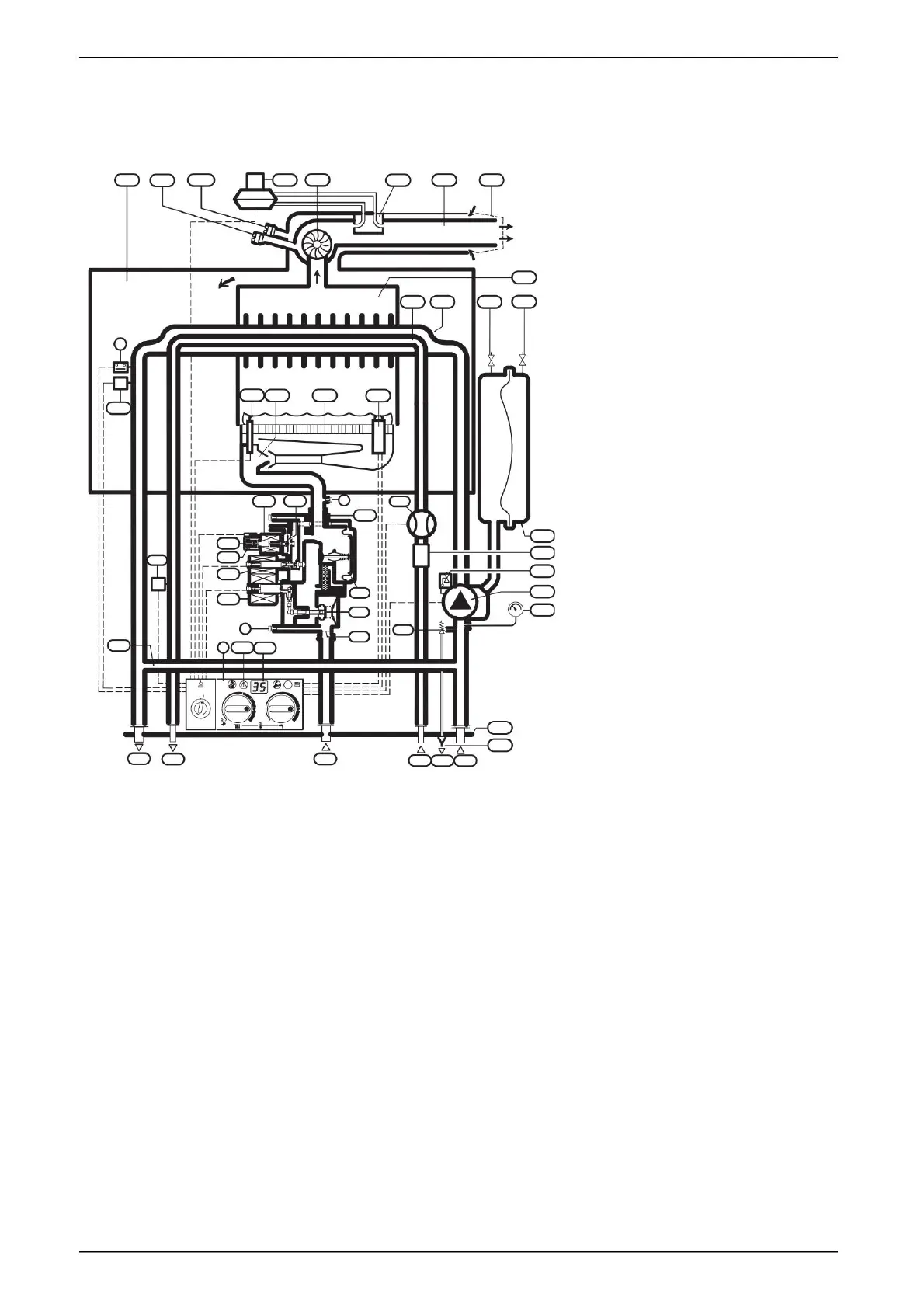
Fig. 2
Power plant information
1.7.1 ZWE 24/28 -4 MFA ...
1.7 Construction of the plant / principle scheme
7 Inlet pressure measuring nozzle
27.1 Automatic deaerator
44
Domestic hot water
52.1 Ventil magnetic 2
93
Water filter flow regulator
317 Multifunction display
20
Expansion vessel
35 Heat exchanger 36 Flow
temperature sensor
48
Drain
63
Maximum gas flow adjustment screw
68
Continuously modulated magnetic valve
228 Differential pressure switch
234 Flue gas measuring nozzle
15
Safety valve (for heating circuit)
30 Burner
Nozzle pressure measuring nozzle
33
Ignition electrode
Heat exchanger temperature limiter
56
Gas valve 57 Main
valve diaphragm
224 Differential pressure probe
13 Connection plate
8.1 Manometer
27.2 Manual deaerator
45 Gas
53
Gas pressure regulator
220 Wind protection
411 Combustion Chamber
3 4 6 6.3 Temperature probe for domestic hot water
43 Heating tour
26
Nitrogen filling valve
52
Ventil magnetic 1
69
Adjusting valve
229 Waterproof chamber
234.1 Combustion nozzle required for combustion
18 Circulation pump
34
Domestic hot water pipe
47
Heating return
Bosch Heatronic
61 Emergency key
64
Minimum gas flow adjustment screw
226 Ventilator
6 720 610 828 RO (02.01)
14
Funnel siphon
11 Bypass line
46
Cold water
32 Ionization electrode
29 Nozzle
55
Gas filter
221 Flue gas piping
413 Domestic hot water flow sensor (turbine)
Machine Translated by Google
 Loading...