1-4 (No.MB177)
SECTION 3
DISASSEMBLY
3.1 Main body section
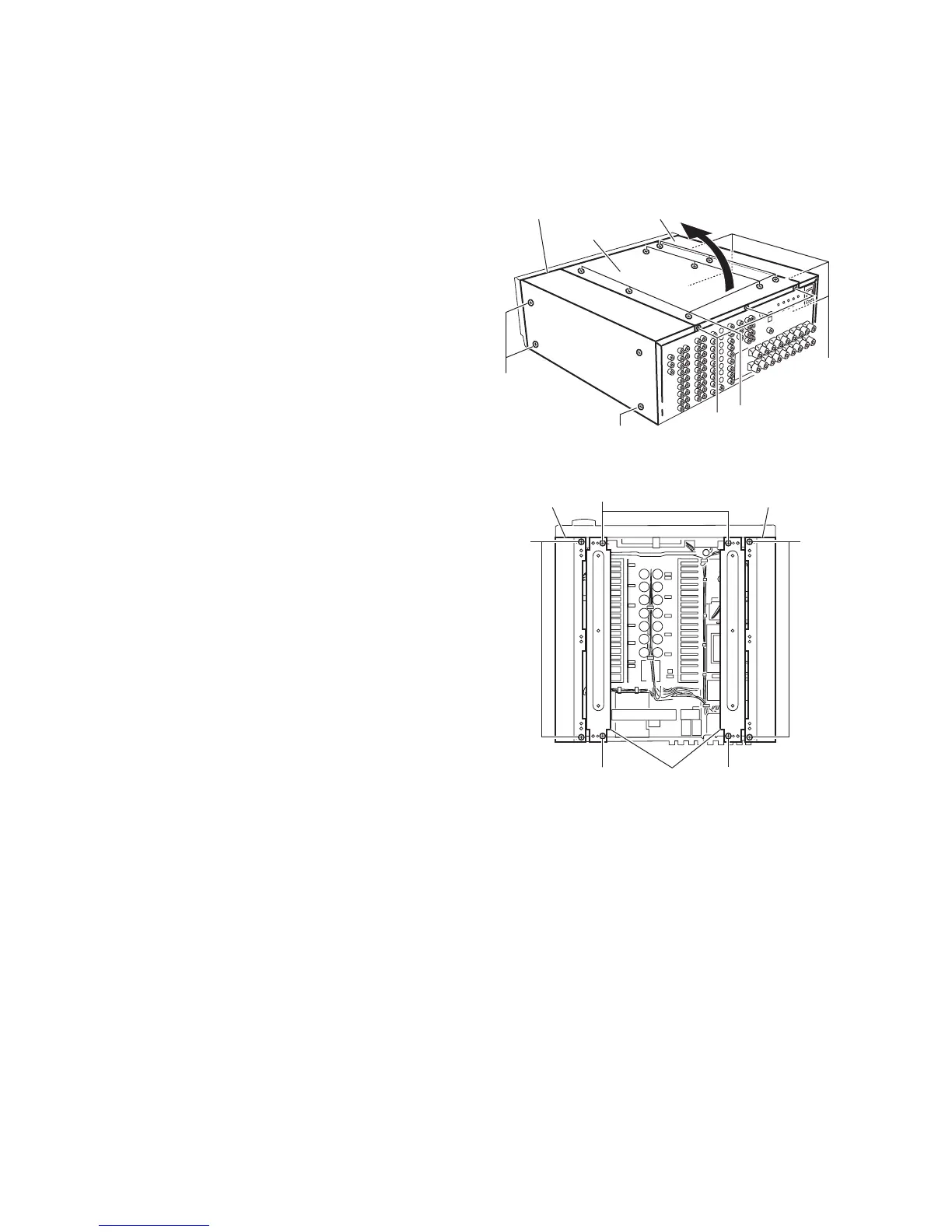
3.1.1 Removing the top cover
(See Fig.1)
(1) From the top sides of the main body, remove the nine
screws A attaching the top cover.
(2) From the back side of the main body, remove the three
screws B attaching the top cover.
(3) Take out the top cover upward in the direction of the arrow.
3.1.2 Removing the side panel (L) & side panel (R) & stay bkt
(See Figs.1 and 2)
• Prior to performing the following procedure, remove the top
cover.
(1) From the left sides of the main body, remove the four
screws C attaching the side panel (L). (See fig.1)
(2) From the right sides of the main body, remove the three
screws C attaching the side panel (R). (See fig.1)
(3) From the top side of the main body, remove the four screws
D attaching the side panel (L) and the side panel (R). (See
fig.2)
(4) Remove the four screws E attaching the stay bkt, and take
out the stay bkt. (See fig.2)
Fig.1
Fig.2
Top cover
C
C
C
B
Side panel (R) Side panel (L)
A
E
E
DD
Side panel(L)
Stay bkt
Side panel(R)
E
 Loading...