4
English
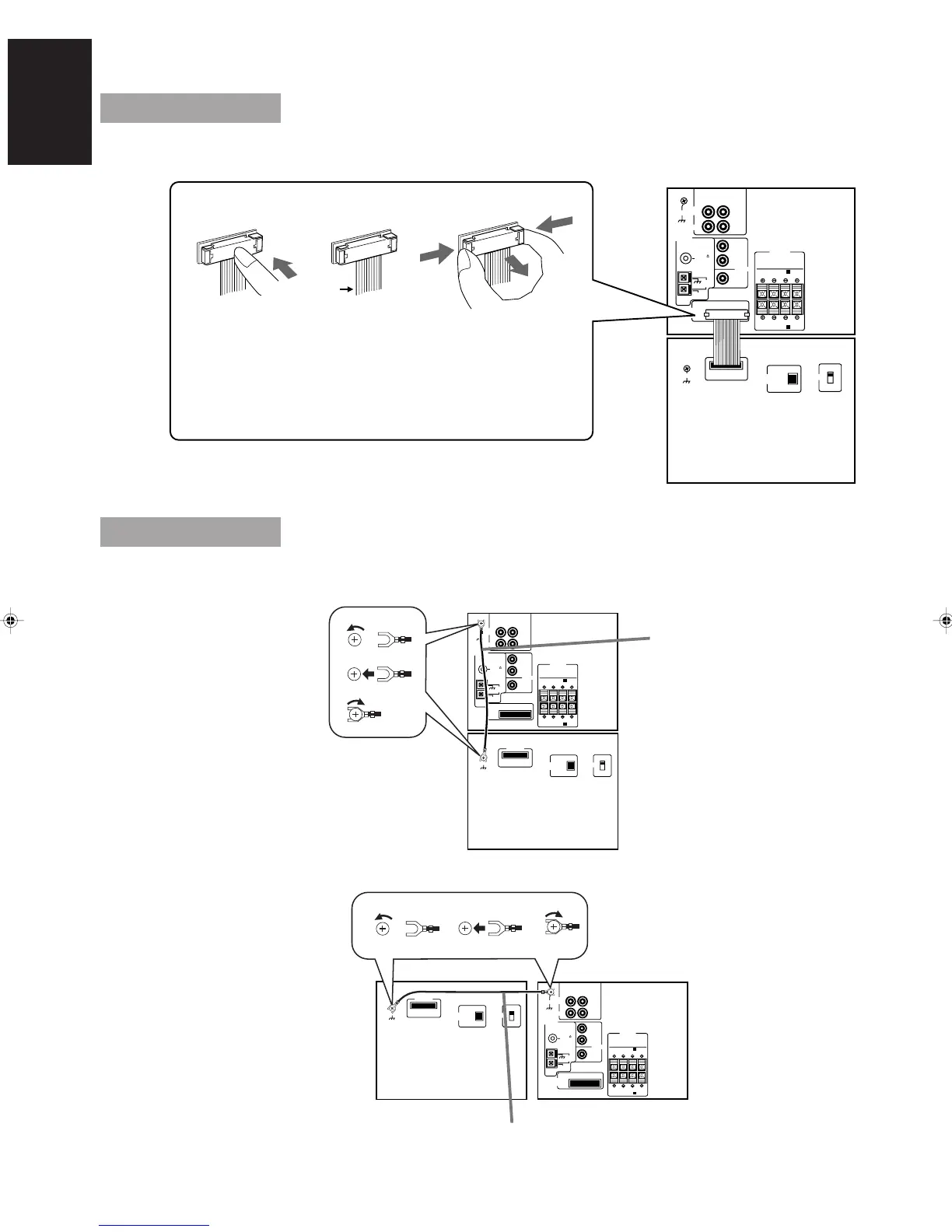
CAUTION: Make all connections before plugging the Unit into an AC power outlet.
Connecting the System Control Cord
Connect the components exactly as illustrated below.
RIGHT
VCR
TV SOUND
VCR
ANTENNA
CONNECTOR
GND
FM 75
COAXIAL
AM
LOOPGND
AM EXT
LEFT
RIGHT LEFT
RIGHT LEFT
IN
(PLAY)
OUT
(REC)
SPEAKERS
SPEAKERS A
SPEAKERS B
CONNECTOR
DIGITAL OUT
OPTICAL
GND
BEAT CUT
1
2
LEFT
RIGHT
CENTER
REAR
PRE OUT
Press the middle of
the connector unit
until it clicks into
the male connector.
When you plug in the
system connector,
make sure that the
white line of the
system connecting
cords is on the left.
While pushing both
ends of the connector,
pull it out.
Never pull on the
cords themselves.
White
line
Connecting the External Wire
CAUTION: To prevent malfunction, connect the supplied wire as illustrated below.
GND
ANTENNA
FM 75
COAXIAL
AM
LOOPGND
AM EXT
CONNECTOR
RIGHT LEFT
RIGHT LEFT
SPEAKERS
SPEAKERS A
SPEAKERS B
CONNECTOR
DIGITAL OUT
OPTICAL
GND
1
2
3
BEAT CUT
1
2
LEFT
RIGHT
CENTER
REAR
PRE OUT
RIGHT
VCR
TV SOUND
VCR
LEFT
IN
(PLAY)
OUT
(REC)
External Wire
RX-TD77R
XT-TD77R
CONNECTOR
RIGHT LEFT
RIGHT LEFT
SPEAKERS
SPEAKERS A
SPEAKERS B
CONNECTOR
DIGITAL OUT
OPTICAL
GND
1
2
3
BEAT CUT
1
2
ANTENNA
FM 75
COAXIAL
AM
LOOPGND
AM EXT
LEFT
RIGHT
CENTER
REAR
PRE OUT
RIGHT
VCR
TV SOUND
VCR
GND
LEFT
IN
(PLAY)
OUT
(REC)
External Wire
RX-TD77RXT-TD77R
CA-TD77R[EF]/EN/p1-25 97.7.24, 3:14 PM4
 Loading...