(No.MB150)1-11
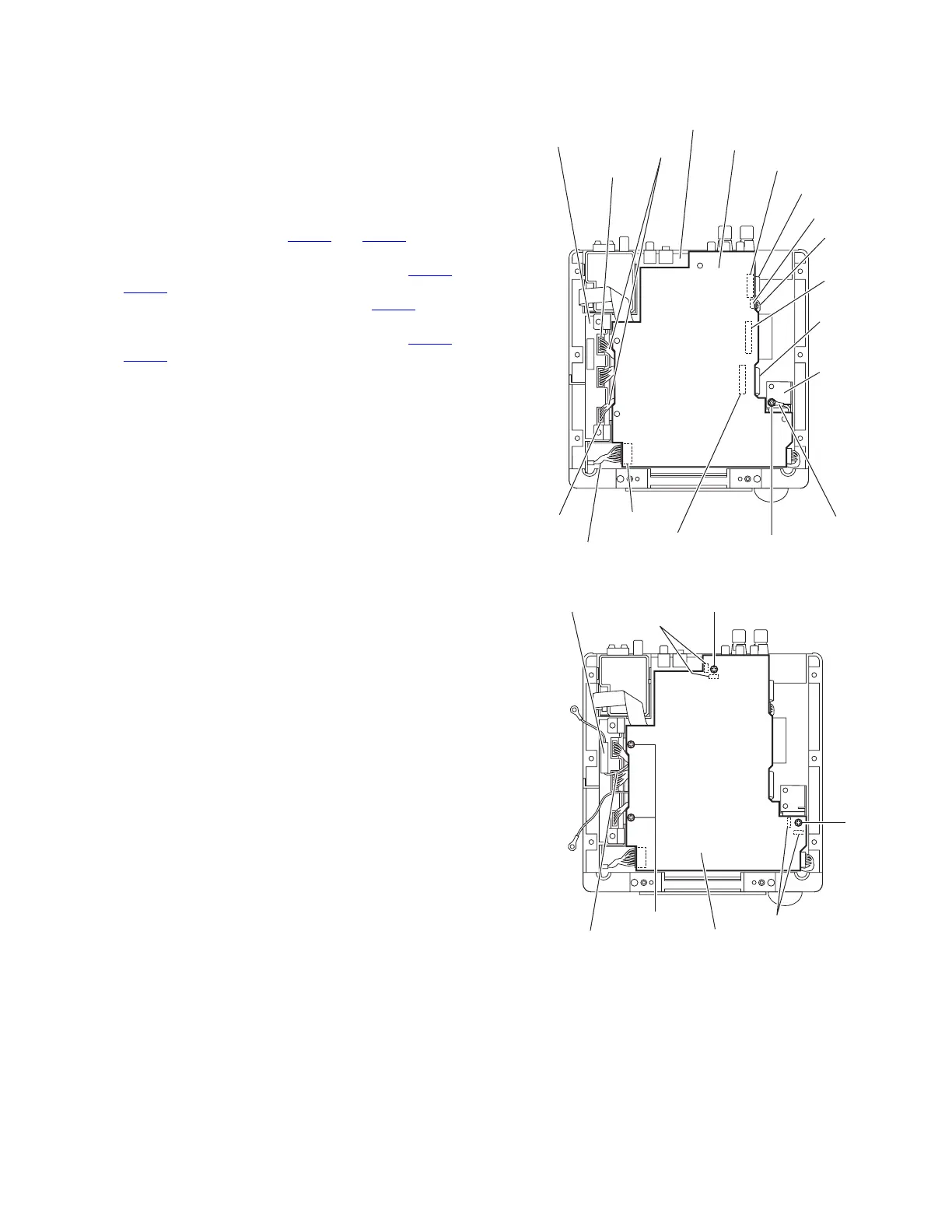
3.1.8 Removing the main board
(See Figs.14 and 15)
• Remove the top cover.
• Remove the AL panel L and AL panel R.
• Remove the rear panel.
• Remove the switching power unit.
Reference:
Remove the front panel assembly as required.
(1) From the top side of the main body, disconnect the card
wires from the connectors CN202
and CN204 on the main
board. (See Fig.14.)
(2) Disconnect the wires from the connectors CN205
and
CN401
on the main board. (See Fig.14.)
(3) Disconnect the wire from the connector CN706
on the mi-
com board. (See Fig.14.)
(4) Disconnect the wires from the connectors CN310
and
CN312
on the digital amplifier board assembly. (See
Fig.14.)
(5) Remove the screw Q attaching the lug wire to the bracket
A. (See Fig.14.)
(6) Remove the spacer fixing the lug wire. (See Fig.15.)
(7) Remove the four screws R attaching the main board and
remove the main board from the main body. (See Fig.15.)
Reference:
When attaching the main board, attach the screw R after fitting
the hole of the main board to the joints e and f of the main
body. (See Fig.15.)
Fig.14
Fig.15
Main board
Micom board
CN204
CN205
CN202
CN401
CN312
CN310
Wire
Card wire
Card wire
Wire
Wires
Digital amplifier
board assembly
CN706
Lug wire
Q
Bracket
Main board
R
R
Spacer
Joints f
Joints e
Lug wire
 Loading...