1-10 (No.MB150)
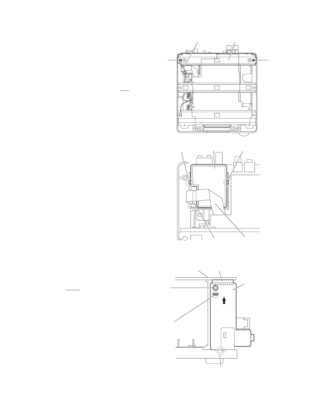
3.1.6 Removing the tuner
(See Figs.11 and 12)
• Remove the top cover.
• Remove the rear panel.
(1) From the top side of the main body, remove the screw N
and screw N' attaching the bridge C. (See Fig.11.)
Reference:
When attaching the screw N', attach the lug wire with it.
(See Fig.11.)
(2) Release the claws b and take out the tuner from the main
body. (See Fig.12.)
(3) Disconnect the card wire from the connector CN1
on the
tuner. (See Fig.12.)
Fig.11
Fig.12
3.1.7 Removing the headphone board
(See Fig.13)
• Remove the top cover.
• Remove the AL panel L and AL panel R.
• Remove the front panel assembly.
(1) From the left side of the main body, disconnect the wire
from the connector CN401
on the main board.
(2) Remove the screw P attaching the headphone board.
(3) Remove the engagement section c toward you, remove the
headphone board from the joint c in the direction of the ar-
row.
Fig.13
Lug wire Bridge C
N
N'
Claw b
Tuner
Claw b
Card wire
CN1
Joint d
Headphone
board
CN401
Main board
P
c
 Loading...