EasyManuals Logo
Home>JVC>Speaker System>EX-A1

JVC EX-A1 User Manual

JVC EX-A1
132 pages
To Next Page IconTo Next Page
To Previous Page IconTo Previous Page
Page #53 background imageLoading...
Page #53 background image
6
Introduction
English
The numbers represent the page numbers.
* Connect a pair of headphones (commercially available) with a stereo mini plug. If the headphones are
connected, the speakers and subwoofer will not produce any sound.
Front panel
PHONES
Play/Pause:13, 15
Look at “Display window” below.
33 35
12,13
STANDBY/ON
: 13
Open/Close
: 13
Headphones
jack*
Disc tray: 13
Remote control
sensor: 7
VOLUME
control: 17
15 15 15
Display window
Upper display
section: 14
18, 23
22
Lower display
section: 14
33
33
35
28
28
18, 23 21 36
27
Rear panel
11
13
13
12 12 12
38 13
10
10
13
Cooling fan (inside)
The fan rotates and stops automatically.
This discharges heat generated inside the unit.
Do not cover up these holes.
Region Code Number: 3
11 11 11 37 12 9 9
10
12
12
12
5
Description of parts
EXA1[UW]-01.fm Page 6 Friday, January 16, 2004 2:08 PM

Table of Contents

Other manuals for JVC EX-A1

Questions and Answers:

Question and Answer IconNeed help?

Do you have a question about the JVC EX-A1 and is the answer not in the manual?
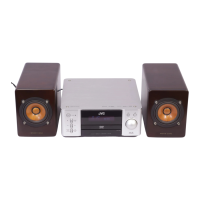
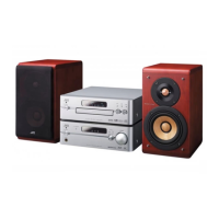
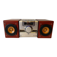
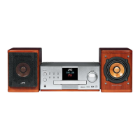
JVC EX-A1 Specifications

General IconGeneral
Speakers2, Real Cherrywood
I/O ports21-pin SCART Out Audio Out (Optical/Subwoofer) Audio In (Analogue) Headphone Out
Output power description2 x 41W
Disc types supportedCD, DVD-R, DVD-RW
Radio Data System (RDS)Yes
Preset stations quantity45
Cassette deckNo
Magnet typeNeodymium
Audio decodersDolby Digital, DTS

Related product manuals