EasyManuals Logo
Home>JVC>Speaker System>EX-A10

JVC EX-A10 Service Manual

JVC EX-A10
105 pages
To Next Page IconTo Next Page
To Previous Page IconTo Previous Page
Page #17 background imageLoading...
Page #17 background image
(No.MB487)1-17
3.1.10 Removing the FL switch board
(See Figs.18 and 19)
Remove the metal cover and front panel assembly.
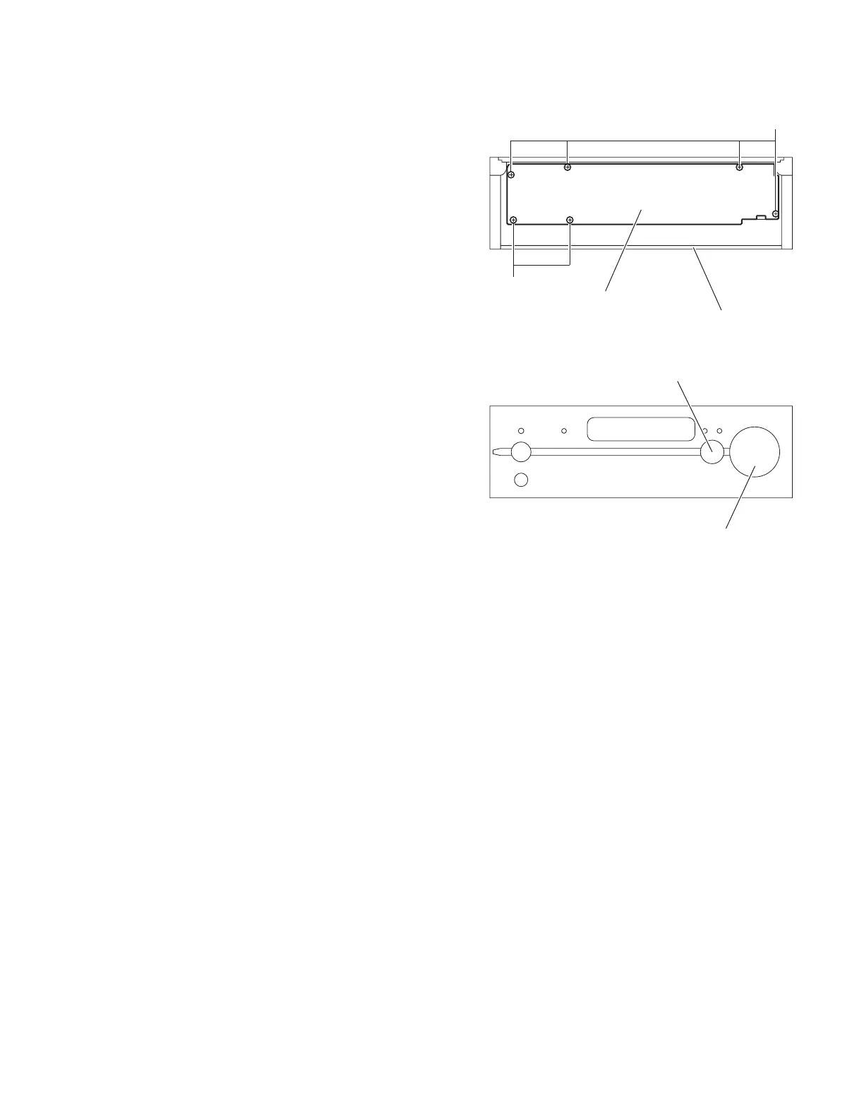
(1) From the inside of the front panel assembly, remove the six
screws Q attaching the FL switch board. (See Fig.18.)
(2) Take out the FL switch board from the front panel assembly
while lifting it little by little. (See Fig.18.)
Reference:
The volume knob assembly and select knob assembly are re-
moved from the front side simultaneously. (See Fig.19.)
Fig.18
Fig.19
FL switch board
Front panel assembly
Q
Q
Volume knob assembly
Select knob assembly

Table of Contents

Other manuals for JVC EX-A10

Questions and Answers:

Question and Answer IconNeed help?

Do you have a question about the JVC EX-A10 and is the answer not in the manual?

JVC EX-A10 Specifications

General IconGeneral
Impedance6 Ω
RMS rated power20 W
EqualizerYes
Volume controlDigital
Supported radio bandsAM, FM
TypeHome audio micro system
Speakers2-Way, Bass-Reflex
Dimensions (WxDxH)245 x 80 x 297 mm
USB 2.0 ports quantity1
Weight and Dimensions IconWeight and Dimensions
Weight2700 g
Center speaker weight3500 g
Center speaker dimensions (WxDxH)143 x 243 x 257 mm

Related product manuals