2-24
2.5.3 PLL operation
X5501
54MHz
TG
V.DRV
IC5501
VCXO
VCO
X3301
81MHz
PHYCLK
PWM405
IC3001
CLK27
VCO
VCOAUDPWMAUD
VCOAUD
ANA_PD
X3001
24.576MHz
MAIN_VCO
MAIN_VCO
ADJ
FS_PLLADJ
JIG CONN
IC3301
FS_PLL
JIG CONN
CLK
OSC
PC
FRP
GEN
81MHz
41.85MHz
Serial I/F
From
DECK_CPU
12.288MHz
11.289MHz
8.192MHz
DVDSP
DVANA
FRP
GEN
MAIN CLK
1394
LINK
REF
1394
PHY
PC
REF
27MHz FRP
FRP
DOMCK
40.5MHz
Not used
REC CLK
IC3101
ANA_DATA
VCO405I
VCO405
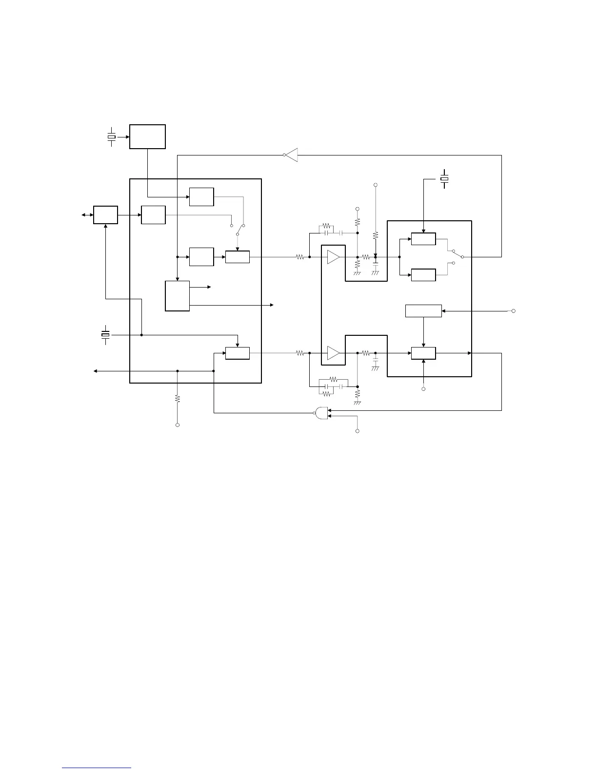
IC3007
Fig. 2-5-3 PLL operation block diagram
The main clock for the deck section operates at a frequency of 40.5MHz, which is equivalent to 18MHz for
the previous models. Since two memories of the SHUFFLE memory and the ECC memory that are
needed for the previous models are integrated into one DRAM, the clock frequency is raised in order to
increase the processing speed. For setting the clock duty ratio exactly at 50
%
, 40.5MHz clock is produced
from the 81MHz clock. The PLL circuit of the main clock system produces 81MHz clock by the X'TAL
X3301 and VCXO, and sends the 81 MHz clock to the IC3001 DV DSP. Using the frame pulse produced
from the 81MHz pulse as the comparison signal of the PLL, the frame pulse (29.97Hz in NTSC or 25Hz in
PAL) is produced from the 27MHz pulse output from the camera and this frame pulse is used as the
reference signal of the PLL in the general recording and playback modes. However, the frame pulse
produced by decoding the input DV signal is used as the PLL reference signal for phase comparison in the
1394 input mode. A phase error is output as the PWM405 signal, which passes through the filter circuit
and controls the VCXO. For PLL adjustment, the filter output voltage is set nearly at the center (1.2V
±
0.1V) of the tolerance in the condition that the PLL is locked.
There are three audio sampling frequencies (32kHz, 44.1kHz and 48kHz) provided, therefore, master
clocks (8.192MHz, 11.289MHz and 12.288MHz) are produced by the VCO in the IC3301 for the
respective sampling frequencies, and those master clocks are output to the IC3001 DV DSP. For adjusting
the FS-PLL, the respective frequencies are adjusted in the free-run status.
 Loading...