SECTION 3
HEAD CLOG WARNING
3-1
3.1 HEAD CLOG WARNING OF DVC
The method and criterion of DVC head clog detection have been changed from this DVC series.
Differently from the previous models which detect head clog in the recording mode only, the new system
incorporated in this series detects head clog in both the recording and playback modes based on the new
detection criterion that is much more strict with possible error as compared with the previous system.
When the head clog warning is occurred on the DVC with the previous detection system, it is impossible to
play back the data correctly rather than the recording data is deteriorated. On the other hand, the DVC
with the new detection system warns the user about deterioration in recording signal because of head
clog.
3.1.1 Structure of Sync Blocks and Error correction
The structure of sync blocks and error correction of the DVC will be explained first. In the digital magnetic
recording and playback system, there is a possibility that random error and burst error caused by signal
dropout in tape occur. Generally, the data transmission systems which quality is not so good adopt the
packet data transmission system for the necessity of frequent reproducing (playback) synchronization.
Therefore, the DVC records data in the form of sync blocks.
One sync block of the AUDIO/VIDEO sector consists of 2 bytes of sync area, 3 bytes of ID code to identify
the attribute of data, and 85 bytes of inner codes. A definite sync pattern is recorded in each sync area. If
the definite sync pattern is not detected in playback, the data in the sync block cannot be restored and
played back. An ID code consists of 3 bytes, namely, 2 bytes of ID and 1 byte of ID parity. The content of
the ID of the AUDIO/VIDEO sector is 4 bits of a sequence number showing the continuity of frames, 4 bits
of track pair number showing the track number, and 8 bits of sync block number showing the row of sync
blocks.
Since the 8-bytes inner parity is added to the AUDIO/VIDEO sector, maximum four errors can be corrected
by this 8-bytes parity and considerable random errors can be corrected also.
Moreover, the 11-bytes outer parity is added to the VIDEO data and 5-bytes outer parity is added to the
AUDIO data. Therefore, burst error caused by signal dropout in tape can be corrected by those parities.
As mentioned above, the optimum error correction strategy with the inner and outer parities is constructed
for intermingled random errors and burst errors in consideration of the dropout characteristic of the tape
medium to be used.
Number of sync blocks in the AUDIO sector is 17 (14 in the data area besides 2 pre-sync blocks and 1
post-sync block). Number of sync blocks in the VIDEO sector is 152 (149 in the data area besides 2 pre-
sync blocks and 1 post-sync block).
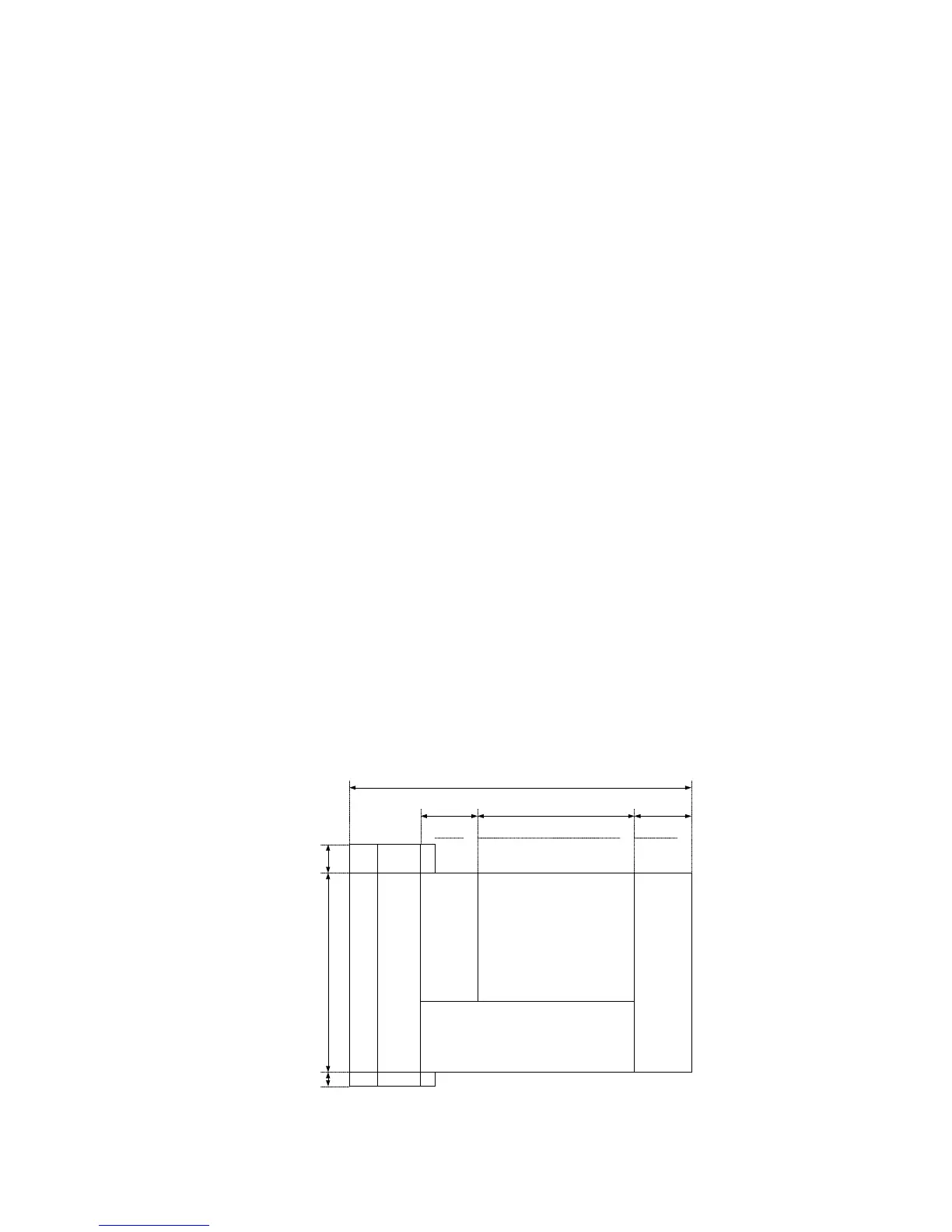
Sync Area
ID
Code
AUDIO
AUX
(AAUX)
AUDIO DATA
Inner
Parity
Outer Parity
Sync block
number
012345 9 81 89
0
1
2
3
4
5
9
6
7
8
10
11
12
13
14
15
16
Byte-position number
Pre-sync
block (2)
Data-sync
block (14)
Post-sync
block (1)
Sync Block length : 90 Byte
5728
Fig. 3-1-1 Structure of sync blocks in audio sector
 Loading...